. 2019 Jun 28;16(155):20190118.
doi: 10.1098/rsif.2019.0118. Epub 2019 Jun 19.

A chordwise offset of the wing-pitch axis enhances rotational aerodynamic forces on insect wings: a numerical study

Affiliations

A chordwise offset of the wing-pitch axis enhances rotational aerodynamic forces on insect wings: a numerical study

Wouter G van Veen et al. J R Soc Interface. .

Abstract

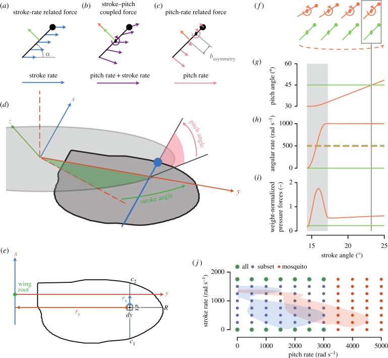
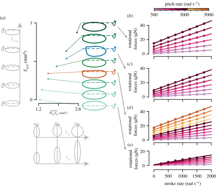
Most flying animals produce aerodynamic forces by flapping their wings back and forth with a complex wingbeat pattern. The fluid dynamics that underlies this motion has been divided into separate aerodynamic mechanisms of which rotational lift, that results from fast wing pitch rotations, is particularly important for flight control and manoeuvrability. This rotational force mechanism has been modelled using Kutta-Joukowski theory, which combines the forward stroke motion of the wing with the fast pitch motion to compute forces. Recent studies, however, suggest that hovering insects can produce rotational forces at stroke reversal, without a forward motion of the wing. We have conducted a broad numerical parametric study over a range of wing morphologies and wing kinematics to show that rotational force production depends on two mechanisms: (i) conventional Kutta-Joukowski-based rotational forces and (ii) a rotational force mechanism that enables insects with an offset of the pitch axis relative to the wing's chordwise symmetry axis to generate rotational forces in the absence of forward wing motion. Because flying animals produce control actions frequently near stroke reversal, this pitch-axis-offset dependent aerodynamic mechanism may be particularly important for understanding control and manoeuvrability in natural flyers.

Keywords: aerodynamic mechanisms; computational fluid dynamics; flapping flight; fruit fly Drosophila hydei; malaria mosquito Anopheles coluzzii; wing morphology.


Conflict of interest statement

We declare we have no competing interests.

Figures

Figure 1.
Figure 1.
(ac) A two-dimensional schematic of the stroke-rate related force, the stroke–pitch coupled force, and the pitch-rate related force on a wing, respectively (equations (2.1) and (2.2)). The circle and diamond indicate the leading edge and pitch axis location, respectively. The green and orange arrows show stroke-rate related force and rotational force, respectively. (a) Blue arrows show wing velocity due to stroke movement. (b) Purple arrows show the wing-velocity distribution due to the combined stroke–pitch movement. (c) Pink arrows show the wing velocity due to the pitch movement; basymmetry is pitch asymmetry. (d) The fruit fly wing in the world reference frame, including the wing reference frame axes (attached to the wing), the stroke plane (in light grey), stroke angle, and pitch angle (angle between the stroke plane and the wing surface). (e) Wing geometry parameters for calculating the second-moment-of-area parameters Sxx, Syy and Sx|x|. (fi) The kinematics and forces used to estimate rotational force production, where data in orange are for the pitching wing, and the green data are of a non-pitching wing (ωpitch = 0 rad s−1); grey area is where the wing is still accelerating around its pitch axis; box with line indicates the stroke angle at which forces are extracted. (f) Schematic of the two wings; the curved dashed line indicates the direction of (revolving) stroke motion; (g) pitch angle versus stroke angle throughout the simulation, (h) pitch rate (solid) and stroke rate (dashed) versus stroke angle, and (i) forces normal to the wing surface versus stroke angle. (j) Parametric space of stroke rate and pitch rate for an average wingbeat of a hovering fruit fly (blue surface) [8] and of a hovering mosquito (red surface) [9]. Dots indicate the stroke rate and pitch rate of all simulations conducted with the mosquito wing (red dots), the fruit fly wing and the symmetric and most asymmetric elliptic wings (blue dots), and all eight tested wings (green dots). (Online version in colour.)
Figure 2.
Figure 2.
(a) The geometry parameters, the stroke–pitch coupled second-moment-of-area √SxxSyy and the asymmetrical second-moment-of-area Sx|x| of the six elliptic wings (green), the fruit fly wing (blue), and the mosquito wing (red). In light-grey along the √SxxSyy-axis are examples of wings with both increasing Sxx and Syy; in light-grey along the Sx|x|-axis is an example of wings with increasing Sx|x|. (be) The rotational forces (difference between total forces and stroke-rate related forces at an angle of attack of 45°) (ordinate) versus the stroke rate (abscissa) and pitch rate (colour-bar above (b)) for the most asymmetric elliptic wing, the fruit fly wing, the mosquito wing, and the symmetric wing, respectively. A linear function was fitted through the dataset at each simulated pitch rate. (Online version in colour.)
Figure 3.
Figure 3.
Testing of the stroke–pitch coupled force model (ac) and the pitch-rate related force model (eg) using our CFD simulations. All data are colour-coded with wing geometry as defined in (d). (a) Stroke-rate slope of stroke–pitch coupled forces Astroke (as defined by equation (3.1)) versus pitch rate for the eight wing geometries (colour coded). Linear functions were fitted through the data for each separate wing. (b) Pitch-rate slope for stroke–pitch coupled forces Apitch (equation (3.2)) versus √SxxSyy, including a linear fit with intercept fixed at zero. (c) Normalized stroke–pitch coupled forces Fstroke-pitch (equation (3.3)) versus pitch rate. The linear fit for each wing has a slope equal to its force coefficient CF,stroke-pitch (equation (2.4)). (e) Pitch-rate related rotational forces Fpitch versus pitch rate, including quadratic fits. (f) Growth factor of these quadratic fits Dpitch (equation (3.4)) versus Sx|x|, including a linear fit. (g) Normalized pitch-rate related forces Fpitch (equation (3.5)) versus pitch rate. The growth factor of the quadratic fit for each wing equals its force coefficient, CF,pitch (equation (2.6)). (Online version in colour.)
Figure 4.
Figure 4.
The aerodynamics of the sub-set of four wings moving at a stroke rate and pitch rate of both 1000 rad s−1. (ad) Schematic of the aerofoil, where the dot indicates the leading edge and the diamond the rotation axis. Pink arrow illustrates the resultant force, Ftotal, blue arrow shows stroke direction, and green arrow indicates the direction of the wing pitch. The forces and their location were obtained by integration of the pressure differences across the wing surface. (eh) The distribution of pressure differences across the wing surface. Dashed line indicates pitch-axis location; green and black lollipops indicate the location of the extraction planes shown in (il) and (mp), respectively. (ip) Pressure and flow field relative to the wing surface extracted from the planes indicated in (eh). (Online version in colour.)
Figure 5.
Figure 5.
The aerodynamics of pitch-rate related force production by the sub-set of four wings moving at a pitch rate of 1000 rad s−1 and a zero stroke rate. (ad) Schematic of the aerofoil (dot indicates leading edge; diamond indicates rotation axis). Pink arrow indicates the pitch-rate related force Fpitch, and green arrow shows the direction of wing pitch. The forces and their location were obtained by integration of the pressure differences across the wing surface. (eh) The distribution of pressure difference across the wing surface. Dashed line shows the pitch axis; black lollipop indicates the location of the extraction plane shown in (ip). (ip) Pressure and flow field in respectively the wing reference frame with subtraction of wing velocity (il) and the wing reference frame without subtraction of wing velocity (mp). (Online version in colour.)
Figure 6.
Figure 6.
The aerodynamics of stroke–pitch coupled force production by the sub-set of four wings moving at both pitch rates and stroke rates of 1000 rad s−1. (ad) Schematic of the aerofoil (dot indicates leading edge; diamond indicates rotation axis). Pink arrow indicates the resultant stroke–pitch coupled force Fstroke-pitch, and green arrow indicates the wing pitch direction. The forces and their location were obtained by integration of the pressure differences across the wing surface. (eh) Distribution of pressure differences across the wing surface. Dashed line indicates the location of the pitch axis; green and black lollipops indicate the location of the extraction planes visualized in (il) and (mp), respectively. (ip) Pressure distributions throughout the planes defined in (eh). All pressures were computed using equation (3.7). (Online version in colour.)
Figure 7.
Figure 7.
Weight-normalized rotational forces throughout the parametric space of stroke rates and pitch rates, for the wingbeat of a hovering fruit fly (ad) and a hovering malaria mosquito (eh). The different components are: (a,e) weight-normalized stroke–pitch coupled rotational forces; (b,f) weight-normalized pitch-rate related forces; (c,g) weight-normalized total rotational forces; (d,h) percentage of pitch-rate related forces relative to the total rotational forces. All forces were estimated using our rotational force model (equation (3.6)). (Online version in colour.)

References

    1. Ellington CP. 1984. The aerodynamics of hovering insect flight. IV. Aeorodynamic mechanisms. Phil. Trans. R. Soc. Lond. B 305, 79–113. (10.1098/rstb.1984.0052) - DOI
    1. van den Berg C, Ellington CP. 1997. The three-dimensional leading-edge vortex of a ‘hovering’ model hawkmoth. Phil. Trans. R. Soc. Lond. B 352, 329–340. (10.1098/rstb.1997.0024) - DOI
    1. Dickinson MH, Lehmann F-O, Sane SP. 1999. Wing rotation and the aerodynamic basis of insect flight. Science 284, 1954–1960. (10.1126/science.284.5422.1954) - DOI - PubMed
    1. Spedding GR, Maxworthy T. 1986. The generation of circulation and lift in a rigid two-dimensional fling. J. Fluid Mech. 165, 247–272. (10.1017/S0022112086003087) - DOI
    1. Birch JM, Dickinson MH. 2003. The influence of wing-wake interactions on the production of aerodynamic forces in flapping flight. J. Exp. Biol. 206, 2257–2272. (10.1242/jeb.00381) - DOI - PubMed

Publication types

LinkOut - more resources