. 2019 Jun 18;6(1):10.
doi: 10.1186/s40658-019-0245-z.

Augmenting camera images with gamma detector data : A novel approach to support sentinel lymph node biopsy

Affiliations

Augmenting camera images with gamma detector data : A novel approach to support sentinel lymph node biopsy

Peter A von Niederhäusern et al. EJNMMI Phys. .

Abstract

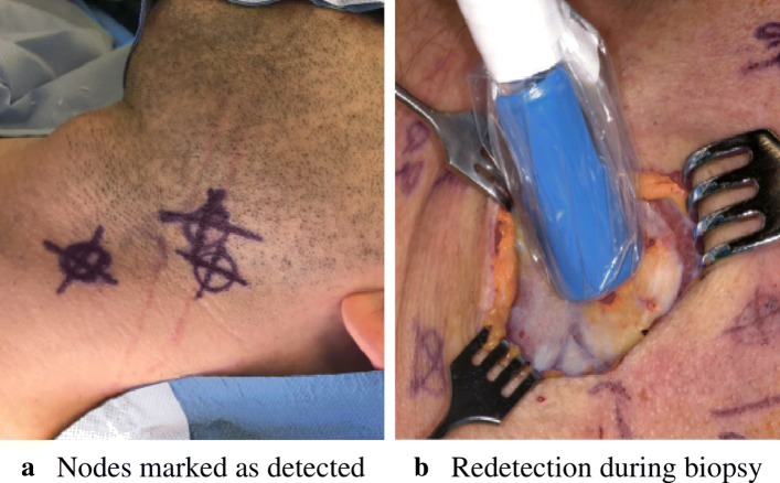
Background: Squamous cell carcinoma in the head and neck region is one of the most widespread cancers with high morbidity. Classic treatment comprises the complete removal of the lymphatics together with the cancerous tissue. Recent studies have shown that such interventions are only required in 30% of the patients. Sentinel lymph node biopsy is an alternative method to stage the malignancy in a less invasive manner and to avoid overtreatment. In this paper, we present a novel approach that enables a future augmented reality device which improves the biopsy procedure by visual means.

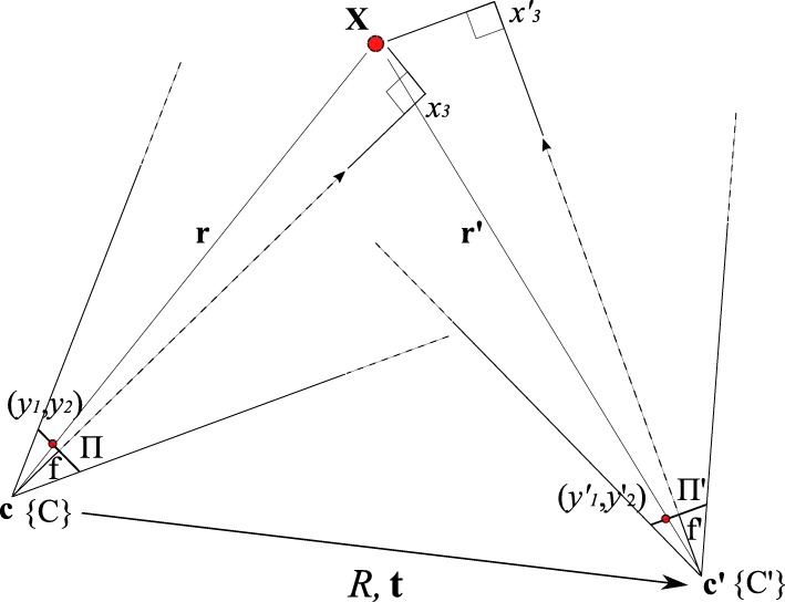
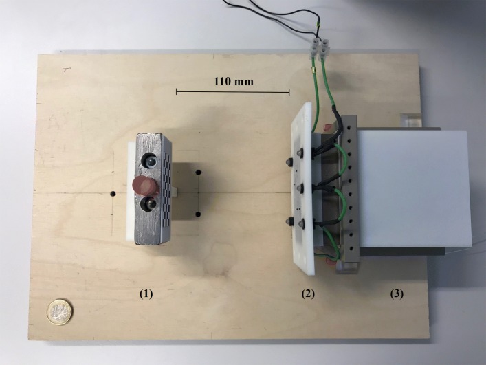
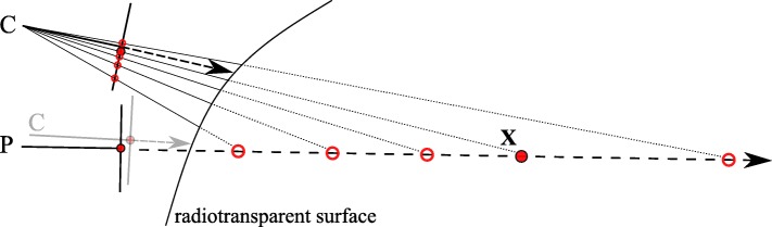
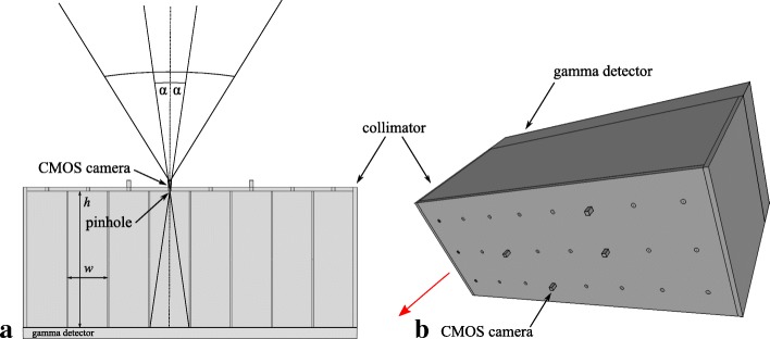
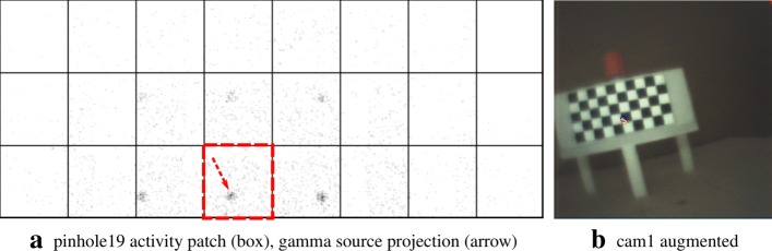
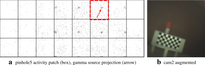
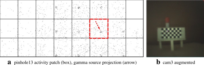
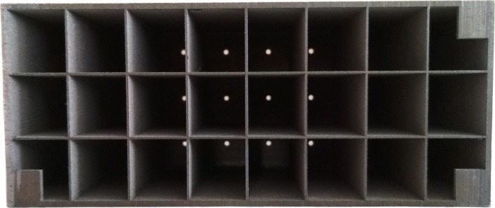
Methods: We propose a co-calibration scheme for axis-aligned miniature cameras with pinholes of a gamma ray collimating and sensing device and show results gained by experiments, based on a calibration target visible for both modalities.

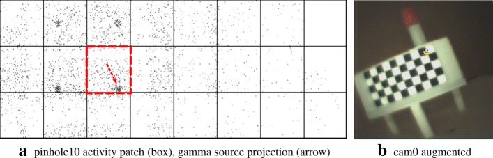
Results: Visual inspection and quantitative evaluation of the augmentation of optical camera images with gamma information are congruent with known gamma source landmarks.

Conclusions: Combining a multi-pinhole collimator with axis-aligned miniature cameras to augment optical images using gamma detector data is promising. As such, our approach might be applicable for breast cancer and melanoma staging as well, which are also based on sentinel lymph node biopsy.

Keywords: Augmented reality; Multi-modality calibration; Projective geometry; Radioguided surgery; Sentinel lymph node biopsy.


Conflict of interest statement

The authors declare that they have no competing interests.

Figures

Fig. 1
Fig. 1
Two consecutive intervention steps of the current SNB procedure: a prior to the intervention, lymph nodes are localized and hand-marked accordingly. b As tissue is pushed away during the biopsy, the lymph nodes need to be redetected using the gamma probe
Fig. 2
Fig. 2
Schematic of a camera pair relation (exaggerated for illustrative purposes) with the corresponding projection of the world point X onto the respective image planes Π,Π. The relative rotation R and translation t are known from calibration. The smaller R and t, the better the co-aligment between both cameras, making the overlay of their respective images possible
Fig. 3
Fig. 3
The pose of the pinhole wrt the target (solid arrows) is known. The pose of the target wrt the camera (dashed arrows) is determined by a pose estimation algorithm. Using the origin {O} as a pivot, we can calculate the rotation R and translation t from {P} to {C}. The tracer is contained inside the vial with the red cap. Exit pupils (blue circles) of the target are used to direct gamma radiation from the tracer for the image augmentation to assess the calibration
Fig. 4
Fig. 4
Calibration setup, viewed from the top. The stand with the calibration target and the vial (red cap) containing the tracer are placed on the left (1). The collimator with the attached camera fixation frame for the microscopic cameras and the LEDs (lighting) are to the right (2). The detector element is adjacent (3). The distance for this measurement is 110 mm from the collimator front plate to the target (calibration default). Not shown is the data processing unit of the detector. A 1-euro coin in the lower left serves as a scale reference
Fig. 5
Fig. 5
An active source (X) is projected along the view axis of the pinhole (P). By not knowing the true depth, any of some possible positions (circles) could be projected onto the image plane of P. This ambiguity cannot be resolved to correctly augment the image produced by the optical camera (C) with information from P. However, by moving C as close as possible to P (light gray), their respective projections converge. Adding a depth estimate improves the accuracy of the image augmentation further. Note the differences between the mapped projections of the image plane of C. We observe that with increasing distance these differences decrease, yielding a decaying error curve (cf. the “Error quantification” section)
Fig. 6
Fig. 6
The camera on the left projects a known world point (X) onto its image plane (y~). The difference ε(px) of the augmentation (y^), based on a depth estimate, is evaluated on the image plane (Π). The difference ε(mm) of its reprojection (X^^) is evaluated on a target plane (Q), given in world units (mm)
Fig. 7
Fig. 7
Simulated disparities ε in millimeter and pixels for different estimated depths, given zero camera rotation and a translation of t=(0.5,0.5,3.0)T mm with respect to the pinhole. The camera is not allowed to move more thanks to constructive constraints. A minimal error is reached where our depth expectation of 110 mm matches the actual depth of the source
Fig. 8
Fig. 8
a Single pinhole of our multi-pinhole collimator, its field of view (2 × α) defined by width w and height h. The wider field of view of the aligned camera is drawn in comparison. b Rendering of the micro camera placement layout with respect to the pinholes (camera fixation frame not shown). The collimator is pointing towards the source (red arrow)
Fig. 9
Fig. 9
Front view of the collimator (rendering). The following camera/pinhole pair layout and naming scheme is used: pair 1 (cam0/ph10), pair 2 (cam1/ph19), pair 3 (cam2/ph5), and pair 4 (cam3/ph13). The layout of the cameras is chosen such that the coverage of the target shows some variability
Fig. 10
Fig. 10
Pair 1, known source distance 90 mm (x3), acquisition time 16 s. a Activity image. b The activity accumulation (orange) of the source near the exit pupil (blue circle) of the Cerrobend TM block is shown
Fig. 11
Fig. 11
Pair 2, known source distance 110 mm (x3), acquisition time 8 s. a Activity image. b Gamma rays emanate near the exit pupil
Fig. 12
Fig. 12
Pair 3, known source distance 130 mm (x3), acquisition time 16 s. a Activity image. b The exit pupil and the activity blob show slight discrepancies
Fig. 13
Fig. 13
Pair 4, known source distance 150 mm (x3), acquisition time 16 s. a Activity image. b The exit pupil and the activity blob match almost exactly
Fig. 14
Fig. 14
Pair 1, true source distance 90mm (x3), initial camera distance 90.8 mm (x3). The curves ε(mm),ε(px) indicate that we are below the maximally allowed error in case the stored initial calibration is used (no automatic pose estimation). However, no apparent minimum is reached in the range of the depth estimates. Depending on the quality of the initial co-calibration at 110 mm, such effects are to be expected
Fig. 15
Fig. 15
Pair 2, true source distance 110 mm (x3), initial camera distance 109.8 mm (x3). Without automatic pose estimation, the error is lowest at the apparent depth of ≈ 90 mm
Fig. 16
Fig. 16
Pair 3, true source distance 130 mm (x3), initial camera distance 124.9 mm (x3). The error curves show their minima at ≈ 140 mm
Fig. 17
Fig. 17
Pair 4, true source distance 150 mm (x3), initial camera distance 150.3 mm (x3). The augmentation error is well below the acceptable error, even if the minimum error is reached at ≈ 140 mm
Fig. 18
Fig. 18
Backside view of the real collimator. Each pinhole yields an activity patch according to its compartment. These compartments define the field of view of the pinholes. Some light-passing pinholes can be seen in the middle
Fig. 19
Fig. 19
A collection of different augmentation results on a neutral target, reusing the respective stored extrinsic calibration of each pair (a-f)
Fig. 20
Fig. 20
Some error cases. The exposure time for these measurements is 16 s. a Overestimating the true distance: estimated distance 150 mm, the augmentation is slightly off. b Underestimating the true distance: estimated distance 110 mm, the discrepancy is visible. c Pathologic case: a ghostly (false) augmentation in the foreground due to high scattering not properly filtered

References

    1. Coskun HH, Medina JE, Robbins KT, Silver CE, Strojan P, Teymoortash A, et al. Current philosophy in the surgical management of neck metastases for head and neck squamous cell carcinoma. Head Neck. 2015;37(6):915–26. doi: 10.1002/hed.23689. - DOI - PMC - PubMed
    1. Calabrese L, Bruschini R, Ansarin M, Giugliano G, De Cicco C, Ionna F, et al. Role of sentinel lymph node biopsy in oral cancer. Acta Otorhinolaryngol Ital: organo ufficiale della Societȧ italiana di otorinolaringologia e chirurgia cervico-facciale. 2006;26(6):345–9. - PMC - PubMed
    1. Radkani P, Mesko TW, Paramo JC. Validation of the sentinel lymph node biopsy technique in head and neck cancers of the oral cavity. Am Surg. 2013;79(12):1295–7. - PubMed
    1. Tsuchimochi M, Hayama K. Intraoperative gamma cameras for radioguided surgery: technical characteristics, performance parameters, and clinical applications. Phys Med. 2013;29(2):126–38. doi: 10.1016/j.ejmp.2012.05.002. - DOI - PubMed
    1. Govers TM, Hannink G, Merkx MAW, Takes RP, Rovers MM. Sentinel node biopsy for squamous cell carcinoma of the oral cavity and oropharynx: a diagnostic meta-analysis. Oral Oncol. 2013;49(8):726–32. doi: 10.1016/j.oraloncology.2013.04.006. - DOI - PubMed