Review
. 2019 Jun 21;8(6):626.
doi: 10.3390/cells8060626.

Inception Mechanisms of Tunneling Nanotubes

Affiliations
Review

Inception Mechanisms of Tunneling Nanotubes

Mitja Drab et al. Cells. .

Abstract

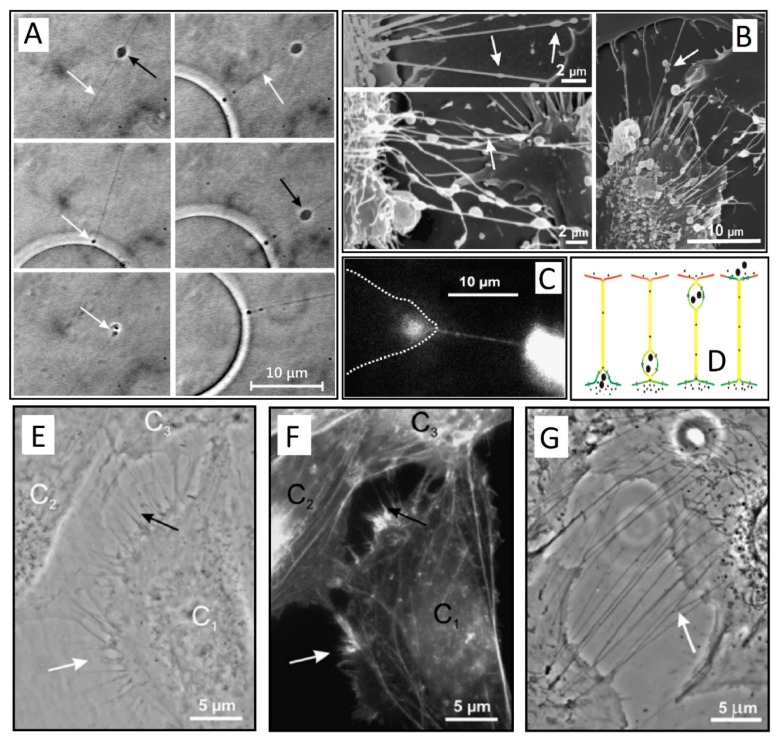
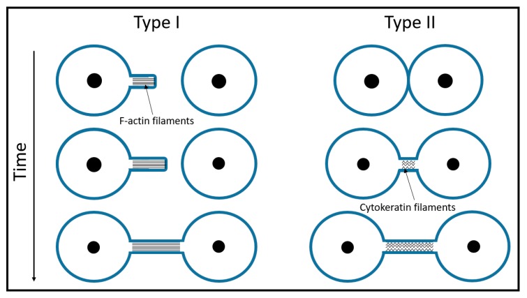
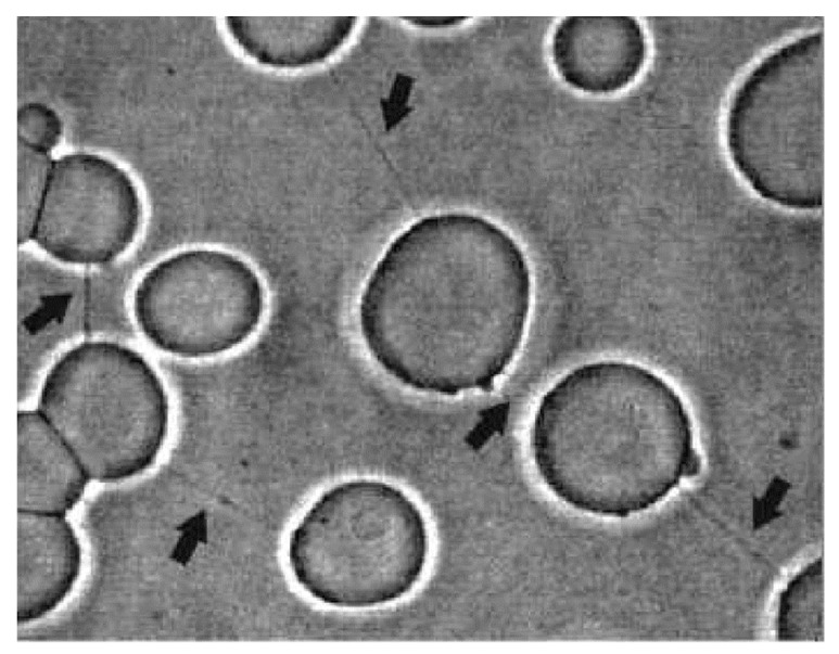
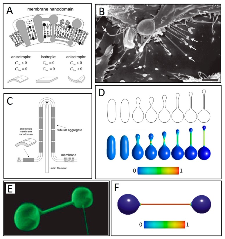
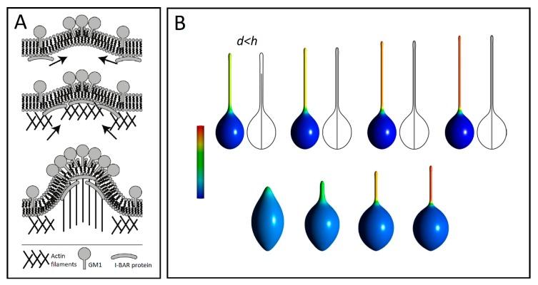
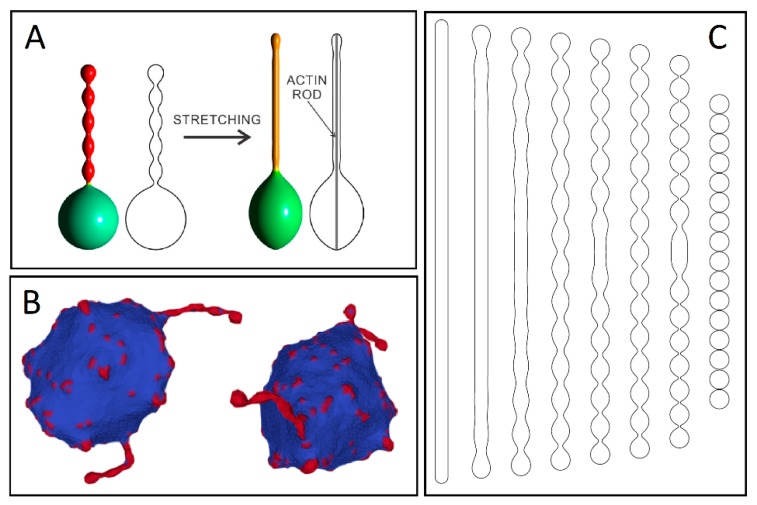
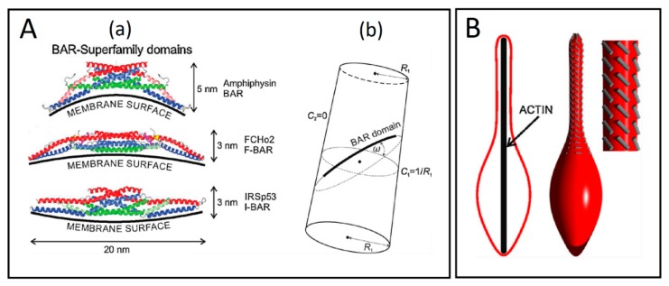
Tunneling nanotubes (TNTs) are thin membranous tubes that interconnect cells, representing a novel route of cell-to-cell communication and spreading of pathogens. TNTs form between many cell types, yet their inception mechanisms remain elusive. We review in this study general concepts related to the formation and stability of membranous tubular structures with a focus on a deviatoric elasticity model of membrane nanodomains. We review experimental evidence that tubular structures initiate from local membrane bending facilitated by laterally distributed proteins or anisotropic membrane nanodomains. We further discuss the numerical results of several theoretical and simulation models of nanodomain segregation suggesting the mechanisms of TNT inception and stability. We discuss the coupling of nanodomain segregation with the action of protruding cytoskeletal forces, which are mostly provided in eukaryotic cells by the polymerization of f-actin, and review recent inception mechanisms of TNTs in relation to motor proteins.

Keywords: anisotropic membrane domains; cytoskeletal forces; f-actin; filopodia; tunneling nanotubes.


Conflict of interest statement

The authors declare no conflict of interest.

Figures

Figure 1
Figure 1
(A) Snapshots of a small gondola (black arrow) traveling along the thin phospholipid tube (white arrow) attached to a spherical giant unilamellar vesicle (GUV). In the final stage, the traveling gondola fused with the membrane of the GUV (white arrow) (adapted from Reference [2]). (B) Scanning electron microscopy of membrane nanotubes with gondolas (white arrows) observed between cells in the human urothelial cell line under physiological conditions (adapted from Reference [11]). (C) Exchange of actin-GFP via a TNT between two T24 cells (cell borders are indicated by a dashed line) (adapted from [11]). (D) A schematic illustration of TNT-directed transport between cells. Note that the gondola is the integral part of the membrane (adapted from Reference [2] and Reference [11]). (E,G) A phase contrast image of live T24 cells with type I TNTs (adapted from Reference [11]). (F) Fluorescence micrograph showing actin labeling of the same cells as in E after 15 min of paraformaldehyde fixation. Cell C1 is approaching the cells C2 and C3. The white arrows in (E,F) indicate short and dynamic membrane protrusion with which the approaching cell explores its surroundings. The black arrow in (E) points at protrusions that have already connected to the target cell. In all these multiple tubular connections, actin filaments are present (arrows in (F)). Bridging type I TNTs can be more than 20 µm in length (arrow in (G)) (adapted from Reference [11]).
Figure 2
Figure 2
A schematic of TNT formation. Type I TNTs contain actin filaments and begin growing like filopodia. Usually, such protrusions appear in bunches of several tubes that dynamically seek connections with neighboring cells. Type II TNTs start growing as neighboring cells move apart. In the case of the urothelial lines RT4 and T24, some actin is still present at the entry point of the Type II tubes at the very beginning of the tube formation [11]. As the tube elongates, the actin gradually disappears and only cytokeratin filaments remain.
Figure 3
Figure 3
POPC–cholesterol–cardiolipin GUVs connected by thin nanotubular connections (indicated by black arrows) (adapted from Reference [50]). The GUVs were prepared by the modified method of electro-formation [43,44].
Figure 4
Figure 4
(A) Schematic figure of three different kinds of intrinsic shapes of flexible membrane nanodomains: partly cylindrical, flat, and saddle-like. Nanodomains with C1m > 0 and C2m < 0 favor saddle-like membrane geometry found in the membrane neck connecting the daughter vesicle to the parent membrane (adapted from Reference [11]). (B) Some of the nanotubes forming between neighboring RT4 urothelial cells have vesicles at their free tips, as indicated by the arrows. Bar = 10 μm. (adapted from [75] -under the Creative Commons 3.0 License). (C) Schematic illustration of stabilization of membrane protrusions by accumulation of anisotropic membrane nanodomains in the tubular region. The cylindrical-shaped anisotropic membrane domains, once assembled in the membrane region of a nanotubular membrane protrusion, keep the protrusion mechanically stable even if the cytoskeletal components (actin filaments) are disintegrated (adapted from Reference [11]). (D) Numerically calculated equilibrium cell shapes for a two-component membrane of isotropic and anisotropic nanodomains with constraint of constant volume. From left to right, intrinsic mean curvature of isotropic membrane components is gradually increased, which results in a more pronounced isotropic-anisotropic segregation given by the color map. The color represents the fraction area covered by isotropic components. The fully blue color corresponds to a membrane composed of isotropic nanodomains only. The shift towards green and red colors indicates increased lateral density of the anisotropic components (adapted from Reference [67] under the Creative Commons 3.0 License). (E) Nanotube–vesicle network stained with the membrane dye DiO (adapted from Reference [39]). (F) The calculated equilibrium closed membrane shape obtained in a system of isotropic components and anisotropic components drawn without the inclusion of the entropy term (adapted from Reference [76]).
Figure 5
Figure 5
(A) A schematic diagram for the recruitment of I-BAR domain proteins and actin filaments by GM1 aggregates (adapted from Reference [10]). (B) Numerically calculated equilibrium cell shapes for different lengths d of the actin rod-like structure enclosed inside the vesicle of height h. All vesicles have the same relative volume (0.9). Apart from the top-left vesicle shape, d = h. The mixing entropy term was considered only for the second row. The color represents the fraction area covered by isotropic components. The fully blue color corresponds to a membrane composed of isotropic nanodomains only, while the yellow and red colors denote high concentrations of anisotropic components (adapted from Reference [92]).
Figure 6
Figure 6
(A) Vesicle shapes calculated for two-component membrane, where one component has high positive intrinsic curvature. The red color represents the highest possible concentration of the membrane component with high intrinsic curvature (adapted from Reference [92]). (B) The results of the Monte Carlo simulation for non-axisymmetric vesicle shape without actin cytoskeleton (adapted from Reference [94]). (C) Analytically calculated axisymmetric vesicle shapes at small relative volume, calculated by minimization of the local membrane bending energy [95]. The calculated series of shapes is constrained by two limiting shapes, i.e. tubular vesicles on the left and necklace-like shapes on the right hand side of series of calculated shapes (adapted from Reference [50]).
Figure 7
Figure 7
(A) Schematic presentations of the BAR superfamily domains and the cylindrical surface with the attached rod-like BAR domain. (a) The BAR domains are presented with their typical dimensions and curvature preferences. (b) The flexible rod-like BAR domain attached to the membrane surface of the cylindrical shape, where R1 is the radius of a cylinder. Angle ω is the angle between the normal plane of the first principal curvature C1 and the normal plane in which the BAR domain is lying. C2 is the second principal curvature (adapted from Reference [69]). (B) The impact of external force on the orientation of BAR domains. The lateral orientation of the membrane attached BAR domains (grey lines) is changed, when the vesicle is elongated by external force, which may result from the action of a growing cytoskeleton inside of the vesicle (adapted from Reference [69]).

References

    1. Arrigler V., Hägerstrand H., Kralj-Iglic V., Iglic A., Gomiscek G., Sevsek F. Microtubes and nanotubes of a phospholipid bilayer membrane. J. Phys. A Math. Gen. 2002;35:1533–1549.
    1. Iglič A., Hägerstrand H., Bobrowska-Hägerstrand M., Arrigler V., Kralj-Iglič V. Possible role of phospholipid nanotubes in directed transport of membrane vesicles. Phys. Lett. A. 2003;310:493–497.
    1. Kralj-Iglič V., Iglič A., Bobrowska-Hägerstrand M., Hägerstrand H. Tethers connecting daughter vesicles and parent red blood cell may be formed due to ordering of anisotropic membrane constituents. Colloids Surf. A Physicochem. Eng. Asp. 2001;179:57–64.
    1. Rustom A., Saffrich R., Walther P., Markovic I., Gerdes H.-H. Nanotubular Highways for Intercellular Organelle Transport. Science. 2004;303:1007–1010. doi: 10.1126/science.1093133. - DOI - PubMed
    1. Lou E., Fujisawa S., Morozov A., Barlas A., Romin Y., Dogan Y., Gholami S., Moreira A.L., Manova-Todorova K., Moore M.A.S. Tunneling Nanotubes Provide a Unique Conduit for Intercellular Transfer of Cellular Contents in Human Malignant Pleural Mesothelioma. PLoS ONE. 2012;7:33093. doi: 10.1371/journal.pone.0033093. - DOI - PMC - PubMed

Publication types

MeSH terms

Substances

LinkOut - more resources