. 2019 May;475(2225):20190012.
doi: 10.1098/rspa.2019.0012. Epub 2019 May 29.

Postbuckling analyses of frame mesostructures consisting of straight ribbons for mechanically guided three-dimensional assembly

Affiliations

Postbuckling analyses of frame mesostructures consisting of straight ribbons for mechanically guided three-dimensional assembly

Yuan Liu et al. Proc Math Phys Eng Sci. 2019 May.

Abstract

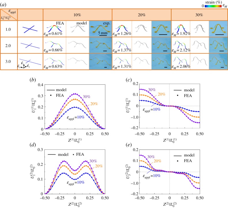
Mechanically guided assembly through buckling-induced two-dimensional (2D)-to- three-dimensional (3D) transformation represents a versatile approach to the formation of 3D mesostructures, thanks to the demonstrated applicability to a wide range of length scales (from tens of nanometres to centimetres) and material types (from semiconductors, metals to polymers and ceramics). In many demonstrated examples of device applications, the 2D precursor structures are composed of ribbon-type components, and some of them exhibit frame geometries consisting of multiple straight ribbons. The coupling of bending/twisting deformations among various ribbon components of the frame mesostructures makes the analyses more complicated than the case with a single component, which requires the development of a relevant theory to serve as the basis of design optimization in practical applications. Here, an analytic model of compressive buckling in such frame mesostructures is presented in the framework of energetic approach, taking into account the contributions of spatial bending deformations and twisting deformations. Three different frame geometries are studied, including '+', 'T' and 'H' shaped designs. As validated by the experiments and finite-element analyses (FEA), the developed model can predict accurately the assembled 3D configurations during the postbuckling of different precursor shapes. Furthermore, the theoretical analyses provide approximate analytic solutions to some key physical quantities (e.g. the maximum out-of-plane displacements and maximum strains), which can be used as design references in practical applications.

Keywords: frame structures; modelling; postbuckling; three-dimensional assembly.


Conflict of interest statement

We declare we have no competing interests.

Figures

Figure 1.
Figure 1.
Illustration of the buckling-guided formation, along with the coordinate system and the key geometric parameters. Three different 3D ribbon network structures, including (a,b) ‘+' shaped mesostructure, (c,d) ‘T' shaped mesostructure and (e,f) ‘H' shaped mesostructure, are considered. (Online version in colour.)
Figure 2.
Figure 2.
Experimental, numerical and theoretical studies of the ‘+' shaped mesostructures. (a) Configurations of 3D frame mesostructures with different length ratios (1.0, 2.0 and 3.0) under different levels of compressive strains (0%, 10%, 20% and 30%). The colour of the FEA results represents the magnitude of maximum principal strain. All of the scale bars in the experiments are 5 mm. (b–e) Analytic and FEA results on the distributions of dimensionless out-of-plane displacements and in-plane displacements for the two ribbon components in the frame mesostructures (with L0(2)/L0(1) = 2.0), under different levels of compressive strains. The geometric parameters include (w/L0(1) = 0.04, t = 75 µm and w = 600 µm). (Online version in colour.)
Figure 3.
Figure 3.
Experimental, numerical and theoretical studies of the ‘T' shaped mesostructures. (a) Configurations of 3D frame mesostructures with different length ratios (0.7, 1.0, 1.5 and 2.0) under different levels of compressive strains (0%, 10%, 20% and 30%). The colour of the FEA results represents the magnitude of maximum principal strain. All of the scale bars in the experiments are 5 mm. (b–e) Analytic and FEA results on the distribution of dimensionless out-of-plane displacement, twist angle and in-plane displacements of ribbon-(1) component in the frame mesostructures (with L0(2)/L0(1) = 1.5), under different levels of compressive strains. (f,g) Similar results on the distribution of dimensionless out-of-plane displacement, in-plane displacement of the ribbon-(2) component. The geometric parameters include (w/L0(1) = 0.04, t = 75 µm and w = 600 µm). (Online version in colour.)
Figure 4.
Figure 4.
Experimental, numerical and theoretical studies of the ‘H' shaped mesostructures. (a) Configurations of 3D frame mesostructures with different length ratios (0.5, 1.0, 1.5 and 2.0) under different levels of compressive strains (0%, 10%, 20% and 30%). The colour of the FEA results represents the magnitude of maximum principal strain. All of the scale bars in the experiments are 5 mm. (b–e) Analytic and FEA results on the distribution of dimensionless out-of-plane displacement, twist angle and in-plane displacements of ribbon-(1) component in the frame mesostructures (with L0(2)/L0(1) = 1.5), under different levels of compressive strains. (f,g) Similar results on the distribution of dimensionless out-of-plane displacement, in-plane displacement of the ribbon-(2) component. The geometric parameters include (w/L0(1) = 0.04, t = 75 µm and w = 600 µm). (Online version in colour.)
Figure 5.
Figure 5.
Results of model calculations, approximate solution and FEA on the dimensionless maximum out-of-plane displacements of the two ribbons components in frame mesostructures and the ratio of maximum out-of-plane displacements at three different levels of compressive strains, for the three different frame mesostructures: (a–c) ‘+' shaped mesostructure, (d–e) ‘T' shaped mesostructure and (g–i) ‘H' shaped mesostructure. (Online version in colour.)
Figure 6.
Figure 6.
(a,b) Dimensionless material coordinates of the positions of maximum out-of-plane displacement in ribbon-(1) component for the ‘+' and ‘T' shaped mesostructures, respectively. (c,d) The mode ratios of the ribbon-(2) component for the ‘T' and ‘H' shaped mesostructures, respectively. (Online version in colour.)
Figure 7.
Figure 7.
Results of model calculations, approximate solution and FEA for the maximum principal strain versus the length ratios for the three frame mesostructures, including (a) ‘+' shaped mesostructure, (b) ‘T' shaped mesostructure and (c) ‘H' shaped mesostructure. (Online version in colour.)

References

    1. Noorduin WL, Grinthal A, Mahadevan L, Aizenberg J. 2013. Rationally designed complex, hierarchical microarchitectures. Science 340, 832–837. (10.1126/science.1234621) - DOI - PubMed
    1. Rogers J, Huang Y, Schmidt OG, Gracias DH. 2016. Origami MEMS and NEMS. MRS Bull. 41, 123–129. (10.1557/mrs.2016.2) - DOI
    1. Xu T, Gao W, Xu L-P, Zhang X, Wang S. 2017. Fuel-free synthetic micro-/nanomachines. Adv. Mater. 29, 1603250 (10.1002/adma.201603250) - DOI - PubMed
    1. Bishop D, Pardo F, Bolle C, Giles R, Aksyuk V. 2012. Silicon micro-machines for fun and profit. J. Low Temp. Phys. 169, 386–399. (10.1007/s10909-012-0654-z) - DOI
    1. Siegel AC, Phillips ST, Dickey MD, Lu N, Suo Z, Whitesides GM. 2010. Foldable printed circuit boards on paper substrates. Adv. Funct. Mater. 20, 28–35. (10.1002/adfm.200901363) - DOI