. 2018 Dec:87:108-125.
doi: 10.1016/j.jmp.2018.10.001. Epub 2018 Nov 20.

Rotational-symmetry in a 3D scene and its 2D image

Affiliations

Rotational-symmetry in a 3D scene and its 2D image

Tadamasa Sawada et al. J Math Psychol. 2018 Dec.

Abstract

A 3D shape of an object is N-fold rotational-symmetric if the shape is invariant for 360/N degree rotations about an axis. Human observers are sensitive to the 2D rotational-symmetry of a retinal image, but they are less sensitive than they are to 2D mirror-symmetry, which involves invariance to reflection across an axis. Note that perception of the mirror-symmetry of a 2D image and a 3D shape has been well studied, where it has been shown that observers are sensitive to the mirror-symmetry of a 3D shape, and that 3D mirror-symmetry plays a critical role in the veridical perception of a 3D shape from its 2D image. On the other hand, the perception of rotational-symmetry, especially 3D rotational-symmetry, has received very little study. In this paper, we derive the geometrical properties of 2D and 3D rotational-symmetry and compare them to the geometrical properties of mirror-symmetry. Then, we discuss perceptual differences between mirror- and rotational symmetry based on this comparison. We found that rotational-symmetry has many geometrical properties that are similar to the geometrical properties of mirror-symmetry, but note that the 2D projection of a 3D rotational-symmetrical shape is more complex computationally than the 2D projection of a 3D mirror-symmetrical shape. This computational difficulty could make the human visual system less sensitive to the rotational-symmetry of a 3D shape than its mirror-symmetry.


Figures

Figure 1.
Figure 1.
Rotational-symmetrical objects in real life.
Figure 2.
Figure 2.
Random-dot patterns with (A, C) rotational- and (B, D) mirror-symmetry with two different densities.
Figure 3.
Figure 3.
2D symmetrical figures with 2-, 3-, 4-, and 5-folds. Their symmetry points are indicated by open circles and their symmetry polygons are drawn with dashed lines.
Figure 4.
Figure 4.
Orthographic projections of planar symmetrical figures in Figure 3 from viewing directions slanted 60° from their symmetry axes. Projections of their symmetry points are indicated by open circles. Note that the orthographic projections of the 2- and 4-fold symmetrical figures are also 2-fold symmetrical.
Figure 5.
Figure 5.
(A) Symmetry polygons with 2-, 3-, 4-, 5-folds and their (B) orthographic and (C) perspective projections. The perspective projections of the symmetry points (open circles) can be derived from the perspective projections of the symmetry polygons only if the number of the folds is more than three. Auxiliary lines for finding the symmetry points are rendered in dotted and dashed lines. The projections of the symmetry points cannot be derived from the 2- or 3-fold symmetry polygons alone.
Figure 6.
Figure 6.
Perspective projections of a 3-fold symmetry polygon (equilateral triangle) with its symmetry axis with four different orientations. The four images of the symmetry polygon are identical to one another. The Principal points of the perspective projection are indicated by ‘x’.
Figure 7.
Figure 7.
Orthographic projections of 3D symmetrical objects with 2-, 3-, 4-, and 5-folds. Their symmetry axes are indicated by thick line segments and symmetry polygons are drawn in gray.
Figure 8.
Figure 8.
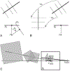
A perspective projection of a 4-fold symmetrical object to the image plane ΠI. The symmetry axis is parallel to a line connecting the vanishing point vaxis of the symmetry axis and the center of projection F. A plane including F and the horizon haxis of the symmetry axis is normal to the symmetry axis and to the segment Fvaxis and are parallel to the symmetry polygons.
Figure 9.
Figure 9.
A perspective projection of a 2-fold symmetrical object. The vanishing points v1, v2, and v3 of the symmetry polygons are collinear on the horizon haxis of the symmetry axis.
Figure 10.
Figure 10.
(A) A perspective projection and another projection after rotating the camera (the principal axis and the image plane ΠI) for σv about the center of projection F so that the symmetry axis becomes normal to ΠIʹ. (C) The original perspective image (solid) and the image after the rotation (dotted). The image after the rotation can be computed directly by transforming the original 2D image. (B) The transformation of the image by rotating the camera is the same as the image transformation by rotating the 3D scene about F in the opposite direction.
Figure 11.
Figure 11.
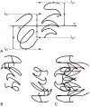
(A) A pair of 2D curves φ and ψ satisfying conditions of Theorem-A1 and (B, C) two views of their 3D symmetrical interpretation. The symmetrical interpretation was constructed by assuming that the slant of its symmetry axis is 45° under an orthographic projection. (B, C) Two orthographic images of the interpretation with its symmetry axis normal to the image plane (B) and with the symmetry axis parallel to the image plane (C). Note that the image in (B) is 2D rotational symmetrical and that in (C) is 2D mirror-symmetrical. These are properties 3D rotational-symmetry under the 2D orthographic projection. See Demo 1 in supplemental material for an interactive illustration of the 3D symmetric curves (the demo is also available at: http://tadamasasawada.com/demos/rotsym/).
Figure 12.
Figure 12.
(A) A pair of 2D curves φ and ψ satisfying conditions of Theorem-A1 and (B, C) two views of their 3D symmetrical interpretation. Some point on one curve in (A) corresponds with multiple points on the other curve and vice versa for the 3D rotational-symmetrical interpretation. The symmetrical interpretation was constructed by assuming that the slant of its symmetry axis is 30° under an orthographic projection. (B, C) Two orthographic images of the interpretation with its symmetry axis normal to the image plane (B) and with the symmetry axis parallel to the image plane (C). Note that the 3D curves of the interpretation of (A) are much more complex than the 2D curves in (A). It is complex because multiple segments of the 3D curves in (B, C) are projected to single segments of the 2D curves in (A). See Demo 2 in the supplemental material for an interactive illustration of the 3D symmetric curves (the demo is also available at: http://tadamasasawada.com/demos/rotsym/).
Figure 13.
Figure 13.
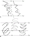
Visual method of establishing the correspondence between a pair of 2D curves for its 3D symmetrical interpretation. The pair of the 2D curves φ (black, solid) and ψ (grey solid) (A) in Figure 11A and (B) in Figure 12A and the 180° rotation of ψ (ψ−1, black dashed). The curve ψ−1 is translated along lφ1 and lφ2 for the clarity of the images. The correspondence between φ and ψ−1 can be established between intersections (black open circles) of φ and ψ−1 with a line (dotted) parallel to lφ1 and lφ2. In (A), the parallel line that intersects with φ has a unique intersection with ψ−1 and vice versa. In (B), the parallel line that intersects with φ has one or a finite number of intersections with ψ−1 and vice versa. The corresponding points on ψ are also indicated by grey open circles.
Figure 14.
Figure 14.
(A) A pair of 2D curves φ and ψ satisfying conditions of Lemma-for-Theorem-A2 and (B, C)two views of their 3D symmetrical interpretation. The symmetrical interpretation was constructed under a perspective projection and its symmetry axis is normal to the image plane. Note that the contours in (A) are identical with those in Figure 11A to allow a comparison between the 3D symmetrical interpretations under the perspective (B, C) and the orthographic (Figure 11B, C) projections. The Principal points of the perspective projection are indicated by ‘x’. (B, C) Two orthographic images of the interpretation with its symmetry axis normal to the image plane (B) and with the symmetry axis parallel to the image plane (C). The orthographic projection is used in (B, C) to show the properties of 3D rotational-symmetry under a 2D orthographic projection (Figure 11): the image in (B) is 2D rotational-symmetrical and the image in (C) is 2D mirror-symmetrical. See Demos 3 and 4 in the supplemental material for an interactive illustration of the 3D symmetric curves (the demos are also available at: http://tadamasasawada.com/demos/rotsym/).
Figure 15.
Figure 15.
A pair of 2D curves φ and ψ satisfying conditions of Theorem-A2. The symmetrical interpretation was constructed under a perspective projection (see Demo 5 in the supplemental material for an interactive illustration of the 3D symmetric curves, the demo is also available at: http://tadamasasawada.com/demos/rotsym/). The Principal points of the perspective projection are indicated by ‘x’. The symmetry axis of the 3D interpretation is oriented so that its vanishing point appears at vaxis. The visual angles from vaxis to uφ1 and to uψ2 are equal to one another and those from vaxis to uψ1 and to u φ2 are also equal to one another.
Figure 16.
Figure 16.
The transformations of the image in Figure 15 after the camera has rotated (A) RcY and (B) RcYRcX. (A) The transformed image after RcY (solid-black) is superimposed to the original image (dotted-grey). (B) The transformed image after RcYRcX (solid-black) is superimposed to the transformed image after RcY (dotted-grey). The Principal points of the perspective projection are indicated by ‘x’.
Figure 17.
Figure 17.
An orthographic projection of a rotational-symmetrical object composed of a pair of wedges. Dotted and dashed contours are projections of a symmetrical pair of planar contours of the object. The relationship between their orthographic projections can be represented as a sub-group of the 2D affine transformation (Theorem-B1).
Figure 18.
Figure 18.
Objects composed of planar contours with 2-, 3-, 4-, 10-, and 20-fold symmetry. Three orthographic views of the individual objects are shown in rows.
Figure 19.
Figure 19.
Orthographic views of a surface of revolution from three different viewpoints. The image of the surface of revolution is always mirror-symmetrical under the orthographic projection.
Figure 20.
Figure 20.
Figures with 1-, 2-, 3-, 4-, and 5-axes of 2D mirror-symmetry. The mirror-symmetrical figures are also 2D rotational-symmetrical if the number of the symmetry axes are more than one.

Similar articles

Cited by

References

    1. Barlow HB, & Reeves BC (1979). The versatility and absolute efficiency of detecting mirror symmetry in random dot displays. Vision Research, 19, 783–793. - PubMed
    1. Biederman I (1987). Recognition-by-components: A theory of human image understanding. Psychological Review, 94, 115–147. - PubMed
    1. Biederman I & Gerhardstein PC (1993). Recognizing depth-rotated objects: Evidence and conditions for three-dimensional viewpoint invariance. Journal of Experimental Psychology: Human Perception and Performance, 19, 1162–1182 - PubMed
    1. Binford T (1971). Visual perception by computer. IEEE Conference on Systems and control, Vol. 261,p. 262.
    1. Bingham GP & Muchisky MM (1993a). Center of mass perception and inertial frames of reference. Perception & Psychophysics, 54, 617–632. - PubMed

LinkOut - more resources