. 2019 Jul 21;19(14):2404-2414.
doi: 10.1039/c9lc00340a. Epub 2019 Jun 26.

Open source acoustofluidics

Affiliations

Open source acoustofluidics

Hunter Bachman et al. Lab Chip. .

Abstract

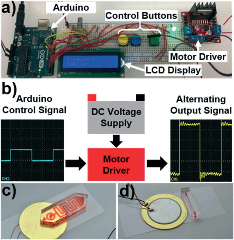
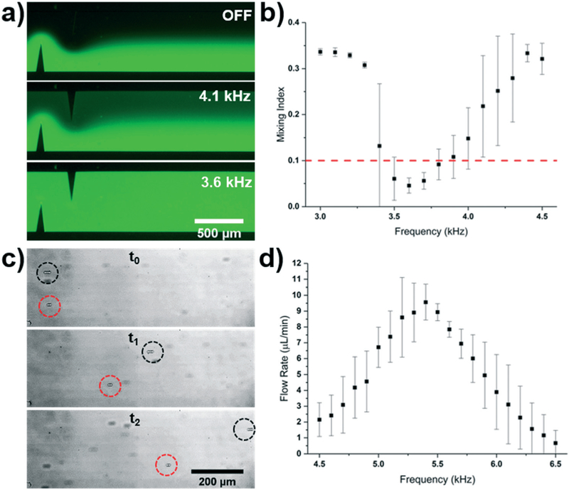
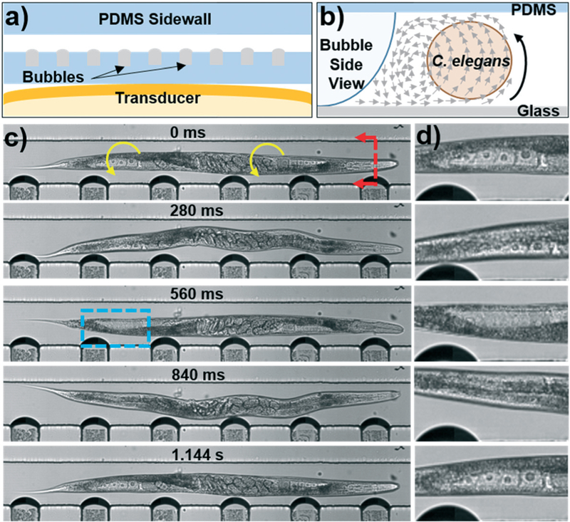
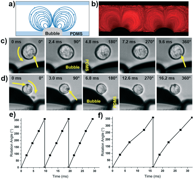
Over the past several decades, a litany of acoustofluidic devices have been developed which purport to have significant advantages over traditional benchtop analytical tools. These acoustofluidic devices are frequently labeled as "labs-on-chips"; however, many do an insufficient job of limiting their dependence on the lab. Often, acoustofluidic devices still require skilled operators and complex external equipment. In an effort to address these shortcomings, we developed a low-cost, expandable, and multifunctional system for controlling acoustofluidic devices in the audible to low ultrasonic frequency range (31 Hz to 65 kHz). The system was designed around the readily available Arduino prototyping platform because of its user-friendly coding environment and expansive network of open source material; these factors enabled us to create a system capable of generating high voltage oscillatory signals and controlling microscale flows in acoustofluidic devices. Utilizing the established open source system, we achieved a series of acoustofluidic applications involving the manipulation of fluids and biological objects in a portable fashion. In particular, we used our open source acoustofluidic devices to achieve active rotation of cells and microorganisms, and operation of an acoustofluidic mixing device which has previously shown potential for viscous sample preparation, in a portable fashion. Additionally, using low frequency flexural waves and our portable system, we achieved acoustofluidic separation of particles based on size. It is our hope that the open source platform presented here can pave the way for future acoustofluidic devices to be used at the point-of-care, as well as simplify the operation of these devices to enable resource limited users to leverage the benefits of acoustofluidics in their work.


Conflict of interest statement

Conflicts of interest

No conflicts to declare.

Figures

Fig. 1
Fig. 1
a) Photo of the open source control platform designed around the Arduino prototyping board. b) Schematic detailing the working mechanism of the control platform. The Arduino provides an alternating signal that controls a motor driver that gates a high voltage source. As the motor driver opens and closes the circuit, the high voltage signal is passed to the transducer in the requisite alternating pattern. Photos of the c) sharp edge based and d) bubble based acoustofluidic devices, which are two of the acoustofluidic devices that are compatible with the platform.
Fig. 2
Fig. 2
a) Fluorescent mixing achieved when applying varying frequencies to the sharp-edge based acoustofluidic device. b) Plot of the mixing index versus frequency for the sharp-edge based acoustofluidic mixer controlled by the Arduino system. A 35 V signal and a 10 μL min−1 total flow rate was used for the mixing experiment. c) Overlaid particle tracing when the sharp-edge based acoustofluidic micropump was operated at two different frequencies. Both particles were pumped with a 30 V signal; the black and red circles track particles pumped using a 5.4 kHz and 6.1 kHz signal, respectively. Time between t0 and t2 was 288 ms. d) Plot of the pumping flow rate versus frequency for the sharp-edge based acoustofluidic micropump controlled by the wall-powered Arduino system. A 30 V signal was applied to the sharp edge pump.
Fig. 3
Fig. 3
a) Schematic of the bubble-based acoustofluidic device. b) Schematic of out-of-plane streaming used to rotate C. elegans. c) Photos taken throughout the rotation of a C. elegans. A 20 V, 19.1 kHz signal was applied to the transducer to induce bubble vibration and C. elegans rotation. The blue box indicates the location of the (d) close-up of the proximal distal gonad provided on the right hand side of each photo. Oocytes can be seen clearly as they rotate into and out of the focal plane of the camera.
Fig. 4
Fig. 4
a) Schematic and b) particle tracing of in-plane rotation using the bubble-based acoustofluidic rotation device and a battery powered Arduino control platform. c) Counterclockwise and d) clockwise bubble-based rotation of HeLa cells using a battery powered Arduino system. The top and bottom cells were rotated via excitation by a 25 V, 20.9, and 21.8 kHz signal, respectively. e) Plot of counterclockwise and f) clockwise rotation angle of cells versus time using the bubble-based acoustofluidic device.
Fig. 5
Fig. 5
a) Photo of the portable syringe pump that is controlled by an Arduino board. b) Flow rate characterization at different rotational speeds of the motor; a linear fit is included with the data (r2 = 0.9995). c) Fluorescent images of mixing in the sputum liquefaction chip with the acoustic signal OFF (left) and ON (right). The acoustic signal was 30 Vpp and 4.8 kHz, with a total flow rate in the channel of 79 μL min−1. d) Trapping and e) release of 20 μm particles using a sharp-edge acoustofluidic device. 2.5 μm particles continue to flow through the channel even when the acoustic signal is on. Red arrows indicate large particle motion, and the bulk flow and small particle movement is marked by the blue arrows.
Fig. 6
Fig. 6
a) Photo of a 1951 USAF resolution target and expanded view of the smallest discernible section. The visible lines in the second element of the seventh group suggests a resolution limit around 3.5 μm. b) Comparative photos of 100 μm wide pillars imaged using the Arduino (top) and benchtop microscope with a 10x objective (bottom). Scale bar is 100 μm. c) Image taken of a C. elegans in the rotation device using the Arduino microscope.

References

    1. Gervais L, De Rooij N and Delamarche E, Adv. Mater, 2011, 23, H151–H176. - PubMed
    1. Chin CD, Linder V and Sia SK, Lab Chip, 2012, 12, 2118–2134. - PubMed
    1. Sia SK and Kricka LJ, Lab Chip, 2008, 8, 1982. - PubMed
    1. Lillehoj PB, Huang MC, Truong N and Ho CM, Lab Chip, 2013, 13, 2950–2955. - PubMed
    1. Liu C, Geva E, Mauk M, Qiu X, Abrams WR, Malamud D, Curtis K, Owen SM and Bau HH, Analyst, 2011, 136, 2069–2076. - PMC - PubMed

Publication types