Dual-modality optical diagnosis for precise in vivo identification of tumors in neurosurgery
- PMID: 31244926
- PMCID: PMC6568186
- DOI: 10.7150/thno.33823
Dual-modality optical diagnosis for precise in vivo identification of tumors in neurosurgery
Abstract
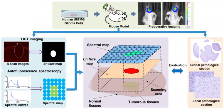
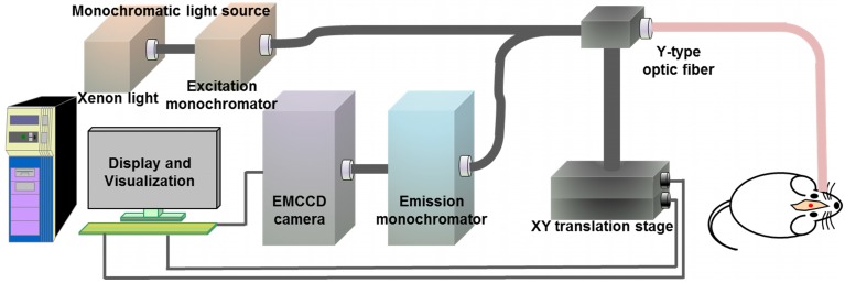
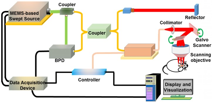
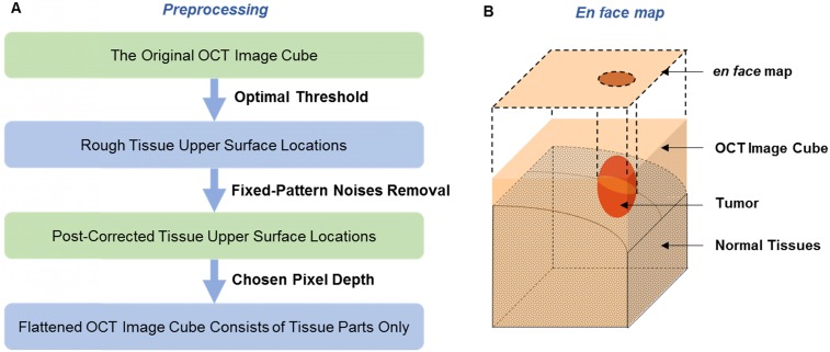
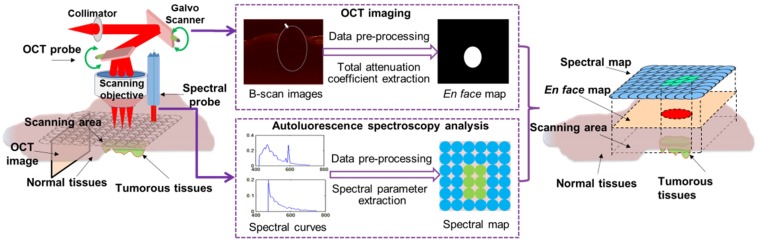
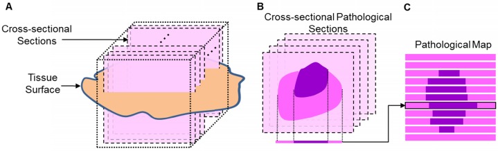
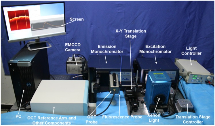
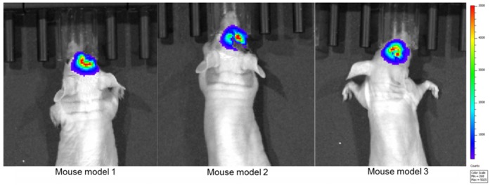
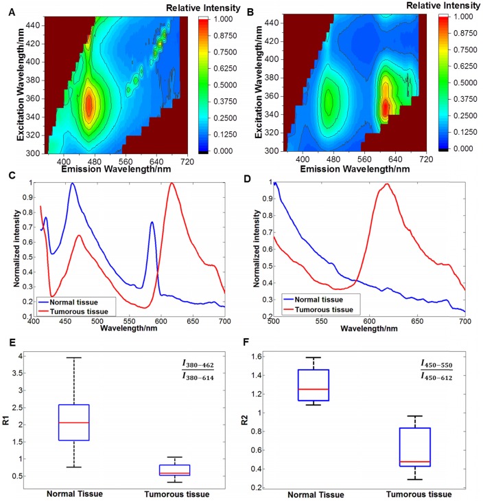
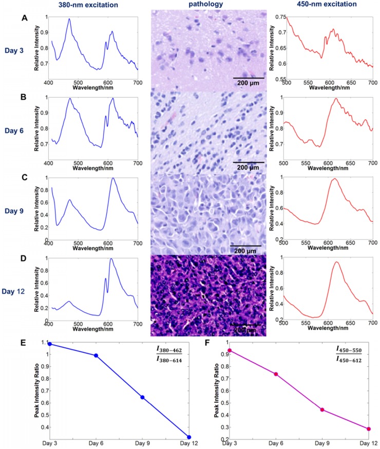
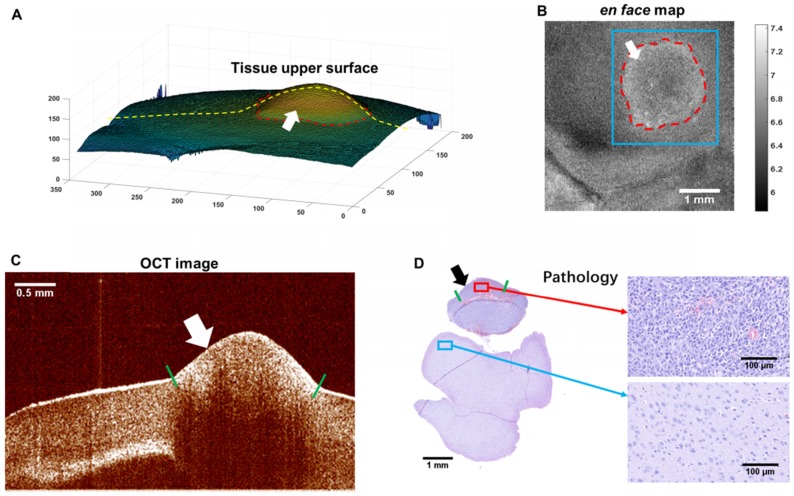
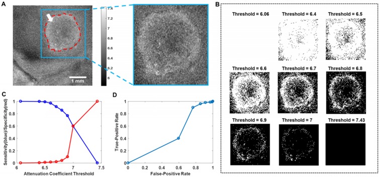
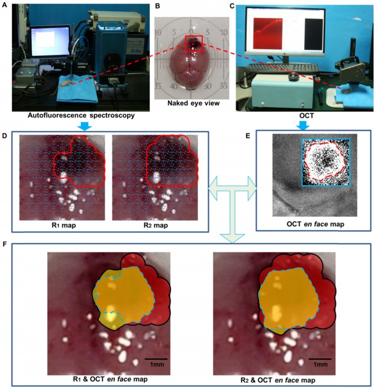
In neurosurgery, the precise diagnosis and treatment of tumor diseases are challenging to realize. Current clinical diagnoses lack fast and accurate intraoperative information. Therefore, the development of new methods and techniques to assist neurosurgeons intraoperatively is necessary. Optical diagnosis is a promising method to provide accurate information about biological tissues in a short time. Therefore, in this study, we proposed a dual-modality optical diagnostic method through point-to-face registration fusion in the optical system. We incorporated quantitative autofluorescence spectroscopy and optical coherence tomography (OCT) and evaluated our methods in an animal model. Methods: A mouse model consisting of 16 nude mice was built by injecting the mouse brains with human glioma cells. Preoperative bioluminescence imaging was used to evaluate the growth states of tumors and locate the tumor sites. Quantitative autofluorescence spectroscopy, which provided local biochemical information with single-point detection, and OCT, which provided relatively global structural information with en face mapping scanning, were combined using the point-to-face registration fusion method to provide precise diagnostic information for identifying the brain tumors. Postoperative pathology was performed to evaluate the sensitivity and specificity of optical diagnosis. Results: Ex vivo quantitative autofluorescence spectroscopy and OCT imaging were first performed in eight mice to acquire the optimal measuring parameters for tumor staging and identification. We then performed in vivo quantitative autofluorescence spectroscopy and OCT imaging. The results showed that tumor staging could be realized through quantitative autofluorescence spectroscopy, and fusion images could be used to precisely identify tumors. The autofluorescence spectral map, OCT en face map, and fused diagnostic map had average sensitivities of 91.7%, 86.1%, and 95.9% and specificities of 93.2%, 96.0%, and 88.7%, respectively, for tumor identification. Conclusion: The dual-modality optical point-to-face registration fusion method and system we proposed could provide both biochemical information and structural information. The in vivo experimental results validated that the sensitivity (95.9%) of the fused map was higher than that of either single diagnostic modality (86.1% or 91.7%). Tumor staging was realized through quantitative autofluorescence spectroscopy. The proposed method will be applicable to future intelligent theranostic systems and improve many clinical neurosurgeries.
Keywords: brain tumor; dual-modality optical diagnosis; neurosurgery; optical coherence tomography; quantitative autofluorescence spectroscopy.
Conflict of interest statement
Competing Interests: The authors have declared that no competing interest exists.
Figures

Similar articles
-
Feasibility evaluation of micro-optical coherence tomography (μOCT) for rapid brain tumor type and grade discriminations: μOCT images versus pathology.BMC Med Imaging. 2019 Dec 30;19(1):102. doi: 10.1186/s12880-019-0405-6. BMC Med Imaging. 2019. PMID: 31888539 Free PMC article.
-
AI-Assisted In Situ Detection of Human Glioma Infiltration Using a Novel Computational Method for Optical Coherence Tomography.Clin Cancer Res. 2019 Nov 1;25(21):6329-6338. doi: 10.1158/1078-0432.CCR-19-0854. Epub 2019 Jul 17. Clin Cancer Res. 2019. PMID: 31315883 Free PMC article.
-
Clinical Characterization of Coronary Atherosclerosis With Dual-Modality OCT and Near-Infrared Autofluorescence Imaging.JACC Cardiovasc Imaging. 2016 Nov;9(11):1304-1314. doi: 10.1016/j.jcmg.2015.11.020. Epub 2016 Mar 9. JACC Cardiovasc Imaging. 2016. PMID: 26971006 Free PMC article.
-
Towards Optical Biopsy in Glioma Surgery.Int J Mol Sci. 2025 May 9;26(10):4554. doi: 10.3390/ijms26104554. Int J Mol Sci. 2025. PMID: 40429698 Free PMC article. Review.
-
Novel real-time optical imaging modalities for the detection of neoplastic lesions in urology: a systematic review.Surg Endosc. 2019 May;33(5):1349-1367. doi: 10.1007/s00464-018-6578-1. Epub 2018 Nov 12. Surg Endosc. 2019. PMID: 30421080 Free PMC article.
Cited by
-
Management of Post-craniotomy Pain in Elective Cases: A Randomized Controlled Trial.Cureus. 2023 Sep 29;15(9):e46189. doi: 10.7759/cureus.46189. eCollection 2023 Sep. Cureus. 2023. PMID: 37905293 Free PMC article.
-
N-mirror Robot System for Laser Surgery: A Simulation Study.Int Symp Med Robot. 2023 Apr;2023:10.1109/ismr57123.2023.10130180. doi: 10.1109/ismr57123.2023.10130180. Epub 2023 May 25. Int Symp Med Robot. 2023. PMID: 38031532 Free PMC article.
-
Intelligent optical diagnosis and treatment system for automated image-guided laser ablation of tumors.Int J Comput Assist Radiol Surg. 2021 Dec;16(12):2147-2157. doi: 10.1007/s11548-021-02457-3. Epub 2021 Aug 7. Int J Comput Assist Radiol Surg. 2021. PMID: 34363584
-
Research progress on the use of the optical coherence tomography system for the diagnosis and treatment of central nervous system tumors.Ibrain. 2024 Nov 22;11(1):3-18. doi: 10.1002/ibra.12184. eCollection 2025 Spring. Ibrain. 2024. PMID: 40103695 Free PMC article. Review.
-
Robotics and optical coherence tomography: current works and future perspectives [Invited].Biomed Opt Express. 2025 Jan 16;16(2):578-602. doi: 10.1364/BOE.547943. eCollection 2025 Feb 1. Biomed Opt Express. 2025. PMID: 39958851 Free PMC article. Review.
References
-
- Allemani C, Matsuda T, Di Carlo V, Harewood R, Matz M, Nikšić M. et al. Global surveillance of trends in cancer survival 2000-14 (CONCORD-3): analysis of individual records for 37 513 025 patients diagnosed with one of 18 cancers from 322 population-based registries in 71 countries. Lancet. 2018;391:1023–75. - PMC - PubMed
-
- Asthagiri AR, Pouratian N, Sherman J, Ahmed G, Shaffrey ME. Advances in brain tumor surgery. Neurol Clin. 2007;25:975–1003. - PubMed
Publication types
MeSH terms
LinkOut - more resources
Full Text Sources
Research Materials