

Inertial measurement unit-based pose estimation: Analyzing and reducing sensitivity to sensor placement and body measures
- PMID: 31245025
- PMCID: PMC6582294
- DOI: 10.1177/2055668318813455
Inertial measurement unit-based pose estimation: Analyzing and reducing sensitivity to sensor placement and body measures
Abstract
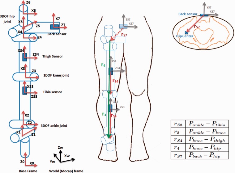
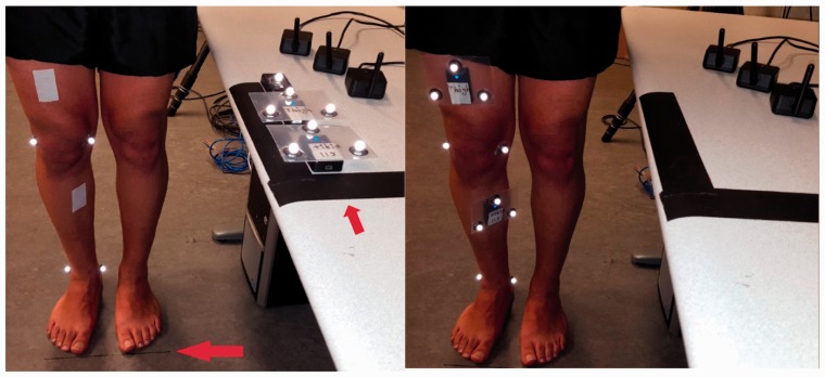
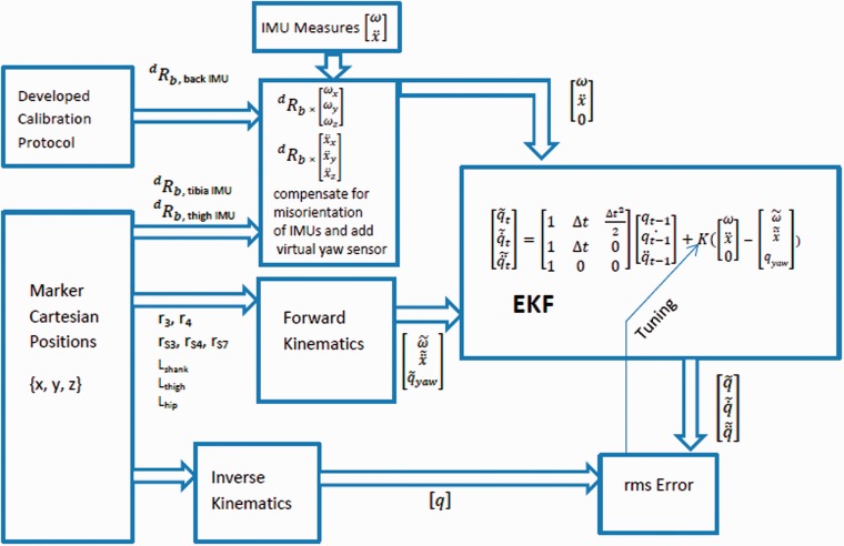
Introduction: Inertial measurement units have been proposed for automated pose estimation and exercise monitoring in clinical settings. However, many existing methods assume an extensive calibration procedure, which may not be realizable in clinical practice. In this study, an inertial measurement unit-based pose estimation method using extended Kalman filter and kinematic chain modeling is adapted for lower body pose estimation during clinical mobility tests such as the single leg squat, and the sensitivity to parameter calibration is investigated.
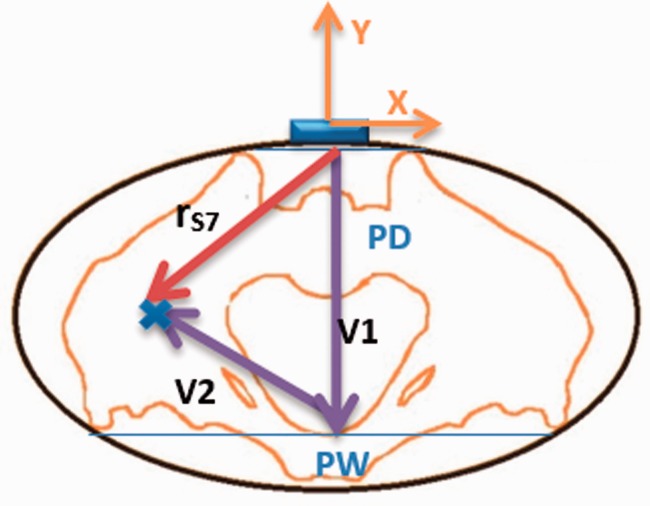
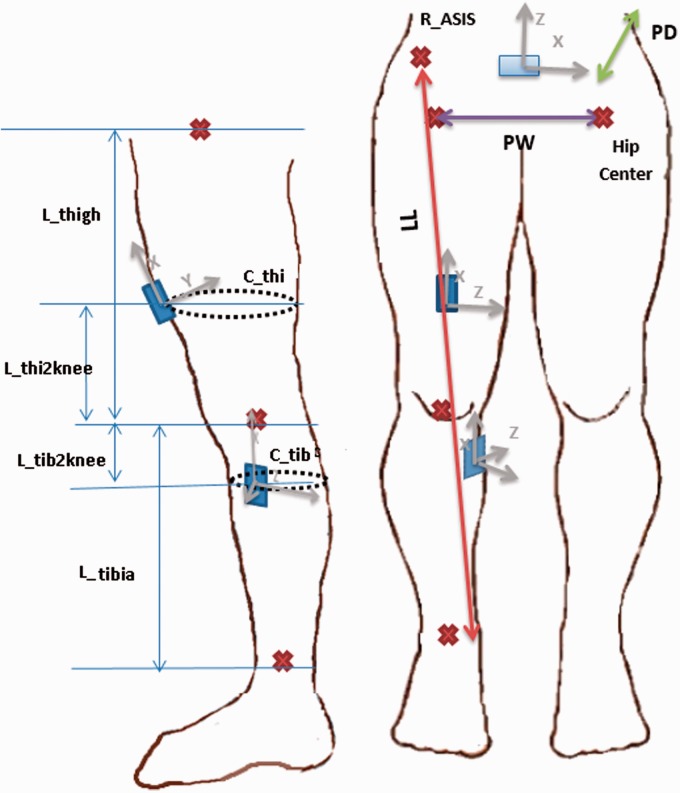
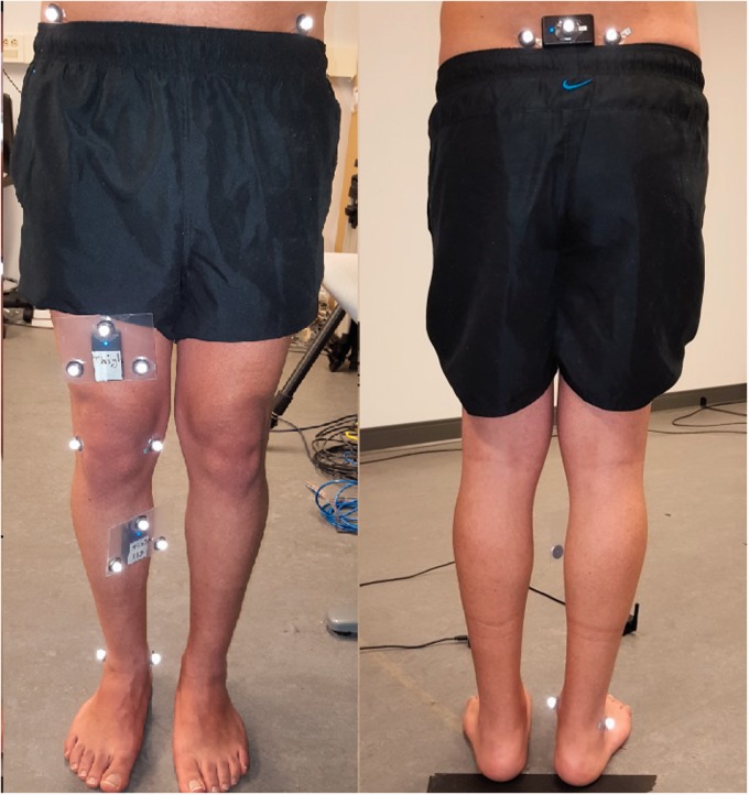
Methods: The sensitivity of pose estimation accuracy to each of the kinematic model and sensor placement parameters was analyzed. Sensitivity analysis results suggested that accurate extraction of inertial measurement unit orientation on the body is a key factor in improving the accuracy. Hence, a simple calibration protocol was proposed to reach a better approximation for inertial measurement unit orientation.
Results: After applying the protocol, the ankle, knee, and hip joint angle errors improved to , and , without the need for any other calibration.
Conclusions: Only a small subset of kinematic and sensor parameters contribute significantly to pose estimation accuracy when using body worn inertial sensors. A simple calibration procedure identifying the inertial measurement unit orientation on the body can provide good pose estimation performance.
Keywords: Inertial measurement unit; calibration; clinical application; extended Kalman filter; forward kinematics; human pose estimation; joint angle; misorientation; sensitivity analysis.
Conflict of interest statement
The author(s) declared the following potential conflicts of interest with respect to the research, authorship, and/or publication of this article: AL and SR are employees of MSK Metrics. DK has received grants from MSK Metrics and the Natural Sciences and Engineering Research Council of Canada.
Figures
References
-
- Hattam P, Smeatham A. Special tests in musculoskeletal examination: an evidence-based guide for clinicians, London, UK: Elsevier Health Sciences, 2010.
-
- DiMattia MA, Livengood AL, Uhl TL, et al. What are the validity of the single-leg-squat test and its relationship to hip-abduction strength? J Sport Rehab 2005; 14: 108–123.
-
- Aristidou A, Lasenby J. Real-time marker prediction and COR estimation in optical motion capture. Visual Comput 2013; 29: 7–26.
-
- Chien-Yen Chang, Lange B, Mi Zhang, et al. Towards pervasive physical rehabilitation using Microsoft Kinect. In: 6th International conference on pervasive computing technologies for healthcare (PervasiveHealth), San Diego, CA, USA, 2012. pp. 159–162. IEEE.
LinkOut - more resources
Full Text Sources
