

Recent advancements on the phase field approach to brittle fracture for heterogeneous materials and structures
- PMID: 31259145
- PMCID: PMC6560700
- DOI: 10.1186/s40323-018-0102-y
Recent advancements on the phase field approach to brittle fracture for heterogeneous materials and structures
Abstract
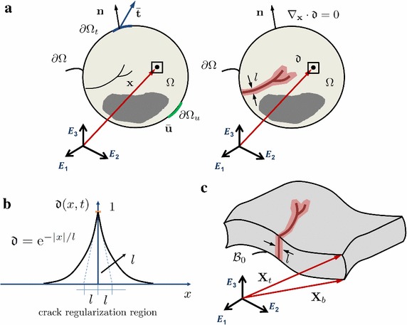
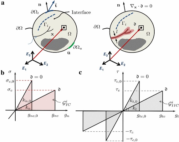
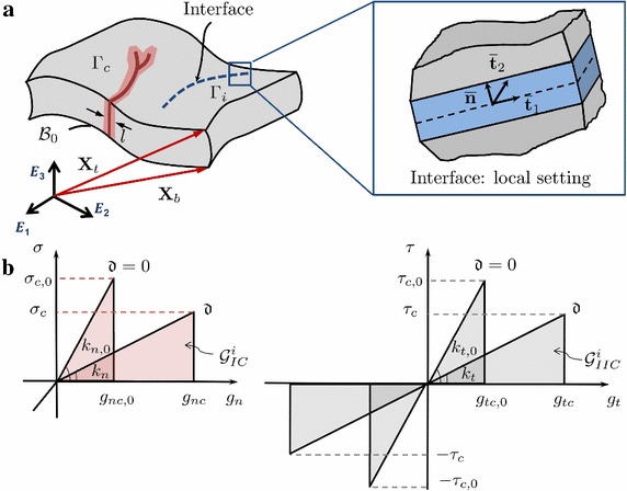
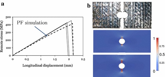
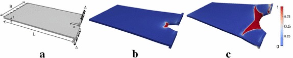
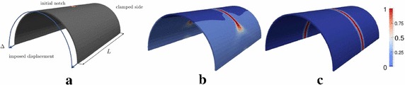
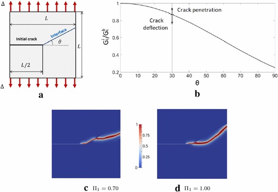
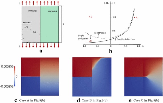
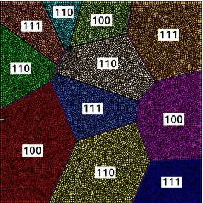
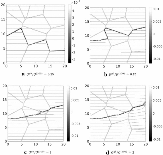
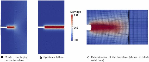
Recent advancements on the variational approach to fracture for the prediction of complex crack patterns in heterogeneous materials and composite structures is herein proposed, as a result of the frontier research activities undertaken in the FP7 ERC Starting Grant project CA2PVM which focuses on the development of computational methods for the durability and the reliability assessment of photovoltaic laminates. From the methodological viewpoint, the phase field approach to describe the propagation of brittle fracture in the bulk has been coupled for the very first time with the cohesive zone model to depict interface crack growth events, for 2D isotropic and anisotropic constitutive laws, and also for 3D finite elasticity. After a summary of the key aspects underlying the theoretical formulation and the finite element implementation using a monolithic fully implicit solution scheme, an overview of the main technological applications involving layered shells, interface mechanical problems and polycrystalline materials is provided. The examples are selected to show the capability of the proposed approach to investigate complex phenomena such as crack deflection vs. crack penetration at an interface, intergranular vs. transgranular crack growth in polycrystals, and interlayer vs. translayer failure in laminates.
Keywords: Cohesive zone model; Heterogeneous materials; Nonlinear finite element method; Phase field model of fracture; Solid shell.
Conflict of interest statement
The authors declare that they have no competing interests.
Figures
Similar articles
-
A phase-field model for fracture in biological tissues.Biomech Model Mechanobiol. 2016 Jun;15(3):479-96. doi: 10.1007/s10237-015-0702-0. Epub 2015 Jul 14. Biomech Model Mechanobiol. 2016. PMID: 26165516
-
A Hybrid Finite Volume and Extended Finite Element Method for Hydraulic Fracturing with Cohesive Crack Propagation in Quasi-Brittle Materials.Materials (Basel). 2018 Oct 9;11(10):1921. doi: 10.3390/ma11101921. Materials (Basel). 2018. PMID: 30304867 Free PMC article.
-
A Particle-Based Cohesive Crack Model for Brittle Fracture Problems.Materials (Basel). 2020 Aug 13;13(16):3573. doi: 10.3390/ma13163573. Materials (Basel). 2020. PMID: 32823584 Free PMC article.
-
XFEM for Composites, Biological, and Bioinspired Materials: A Review.Materials (Basel). 2024 Feb 4;17(3):745. doi: 10.3390/ma17030745. Materials (Basel). 2024. PMID: 38591618 Free PMC article. Review.
-
A Review on Brittle Fracture Nanomechanics by All-Atom Simulations.Nanomaterials (Basel). 2019 Jul 22;9(7):1050. doi: 10.3390/nano9071050. Nanomaterials (Basel). 2019. PMID: 31336659 Free PMC article. Review.
References
-
- Fries T-P, Belytschko T. The extended/generalized finite element method: an overview of the method and its applications. Int J Numer Methods Eng. 2010;84(3):253–304.
-
- Garcia IG, Paggi Marco, Mantič V. Fiber-size effects on the onset of fiber–matrix debonding under transverse tension: a comparison between cohesive zone and finite fracture mechanics models. Eng Fract Mech. 2014;115:96–110. doi: 10.1016/j.engfracmech.2013.10.014. - DOI
-
- Linder C, Armero F. Finite elements with embedded strong discontinuities for the modeling of failure in solids. Int J Numer Methods Eng. 2007;72(12):1391–1433. doi: 10.1002/nme.2042. - DOI
-
- Parmigiani JP, Thouless MD. The roles of toughness and cohesive strength on crack deflection at interfaces. J Mech Phys Solids. 2006;54(2):266–287. doi: 10.1016/j.jmps.2005.09.002. - DOI
Publication types
LinkOut - more resources
Full Text Sources