. 2019 Jun;16(2):223-230.
doi: 10.14245/ns.1938140.070. Epub 2019 Jun 30.

Mechanically Relevant Anatomy of the Axis Vertebra and Its Relation to Hangman's Fracture: An Illustrated Essay

Affiliations

Mechanically Relevant Anatomy of the Axis Vertebra and Its Relation to Hangman's Fracture: An Illustrated Essay

Venugopal K Menon. Neurospine. 2019 Jun.

Abstract

To describe the biomechanically relevant anatomy of the Axis vertebra and the load transfer patterns within the bone, and on that basis, to postulate its mechanism of injury, a literature review was conducted of the anatomy and biomechanics of Axis fractures. Two hypotheses have been presented: the internal gear hypothesis and the leaf spring hypothesis. Both are based on the trabecular anatomy of the vertebra and its load transmission patterns. The relationship of the Axis with Hangman's injury is also discussed. According to the leaf spring hypothesis, the C2 pedicle corresponds to the shackle in the assembly and constitutes the weak link. The trabecular architecture of the Axis is such that the primary compression of the trabeculae is directed from the superior facet to the C2-3 endplate, with few trabeculae directed to the inferior facet. Along with the trabecular void in this area, this renders the isthmus vulnerable to trauma. The isthmus of the Axis is biomechanically susceptible to injury due to its unique anatomy in relation to the whole cervical spine and the internal load transmission patterns of the bone. The author suggests that in the flexion type of Hangman's injury, the C1-2 posterior ligaments are disrupted and need to be addressed.

Keywords: Axis vertebra; Biomechanical phenomena; Cervical vertebrae; Ligaments; Spinal fractures.


Conflict of interest statement

The authors have nothing to disclose.

Figures

Fig. 1.
Fig. 1.
(A) Line diagram of the Axis vertebra; please note the sagittal and axial alignment of the superior and inferior facets depicted with arrows. (B) Line drawing of the sagittal view of the Axis; the sagittal plane alignment of the superior and inferior facets is pointed out by the arrows. Also note that unlike the subaxial cervical spine, the facets are not in a line.
Fig. 2.
Fig. 2.
Figurative representation of the head being supported by the cranio-cervical junction. The bicolumnar support is converted to a tricolumnar support as the loads exit the Axis, represented by the square block. The anterior column is the vertebral body bearing the brunt of the load and the posterior pillars are the facet columns.
Fig. 3.
Fig. 3.
Diagram depicting the load transfer pattern within the C2 vertebra as described in Fig. 2. The body of the axis is removed and the internal force distribution alone is depicted by the arrows.
Fig. 4.
Fig. 4.
Coronal computed tomography section illustrating the trabecular anatomy of the Axis. Please note the primary compression trabeculae run down from the superior facet to the inferior end plate of the vertebral body (arrows).
Fig. 5.
Fig. 5.
Three-dimensional figure of the C2 vertebra depicting the primary compression and secondary compression trabeculae (thin arrows; thick arrows represents the axial loads on the superior facets).
Fig. 6.
Fig. 6.
Sagittal reformatted computed tomography of the Axis illustrating the consistent void in the isthmus of the bone (arrow).
Fig. 7.
Fig. 7.
(A) The vertically oriented leaf spring of a car illustrating its salient components: A´ is the shackle. B´ represents the rebound clips and C´ represents the center bolt. D´ is the spring leaf itself. (B) The clinical depiction of the leaf spring model in the upper cervical spine. The isthmus of the C2 represents the shackle, the pedicles of the vertebrae the rebound clips (B´), and the 3 columns the 3 leaves of the spring system-C´. D´ is the base comprising of the rigid thoracic spine.
Fig. 8.
Fig. 8.
Three-dimensional model of the cervico-thoracic junction as represented by the leaf spring hypothesis. A´ is the Atlas, B´ is the isthmus of the Axis (the shackle of the spring system), C´ is the rebound clips, and D´ & E´ are the spring leaves represented by the load bearing columns of the cervical spine.
Fig. 9.
Fig. 9.
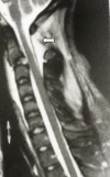
Sagittal magnetic resonance image of a flexion type of Hangman’s fracture. Please note the increased C1–2 interspinous interval and the signal changes suggesting hematoma formation (white arrow).
Fig. 10.
Fig. 10.
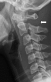
X-ray of a similar flexion type of Hangman’s lesion depicting the increased C1–2 interval suggesting disruption of the posterior ligament complex (white arrow).
Fig. 11.
Fig. 11.
Possible mechanism of the extension type of Hangman’s injury. The curved arrows depict the extension moment and the straight arrows the pincer effect of the facets on the isthmus.
Fig. 12.
Fig. 12.
The flexion type of Hangman’s injury is possibly the result of a 3-point bending moment as illustrated here. The Axis is bent over the fulcrum of the C3 superior facet creating the isthmus fracture.

References

    1. Stulik J, editor. Cervical spine trauma. Praha (Czech Republic): Galen Publishing; 2012.
    1. Benzel EC, editor. Biomechanics of spine stabilisation. New York: Thieme; 2015.
    1. Zdeblick TA, Benzel EC, Anderson PA, Stillerman CB, editors. Controversies in spine surgery. New Delhi (India): Jaypee Publishers; 2004.
    1. Korres DS, editor. The axis vertebra. Italia: Springer Verlag; 2013.
    1. Naderi S, Arman C, Guvencer M, et al. Morphometric analysis of the C2 body and the odontoid process. Turk Neurosurg. 2006;16:14–8.

LinkOut - more resources