Review
. 2019 Jul 8;12(13):1197-1216.
doi: 10.1016/j.jcin.2019.04.052.

Preventing Coronary Obstruction During Transcatheter Aortic Valve Replacement: From Computed Tomography to BASILICA

Affiliations
Review

Preventing Coronary Obstruction During Transcatheter Aortic Valve Replacement: From Computed Tomography to BASILICA

Robert J Lederman et al. JACC Cardiovasc Interv. .

Abstract

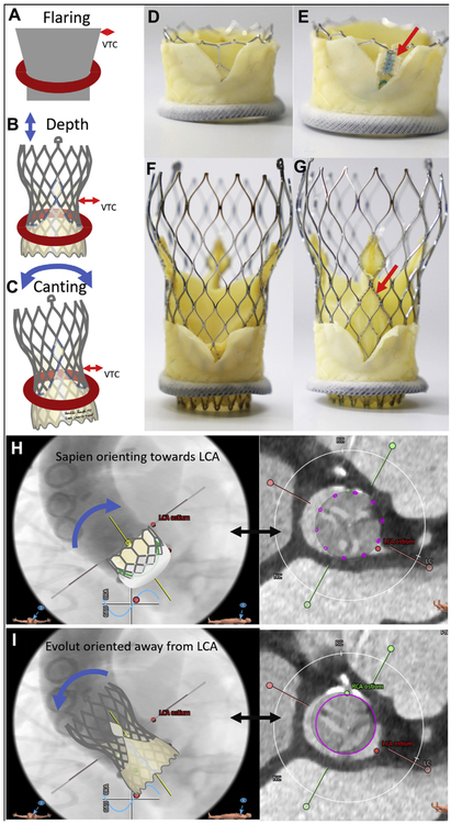
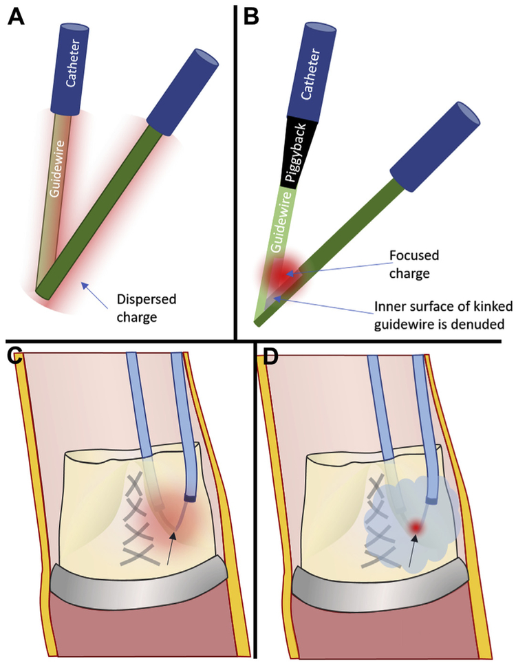
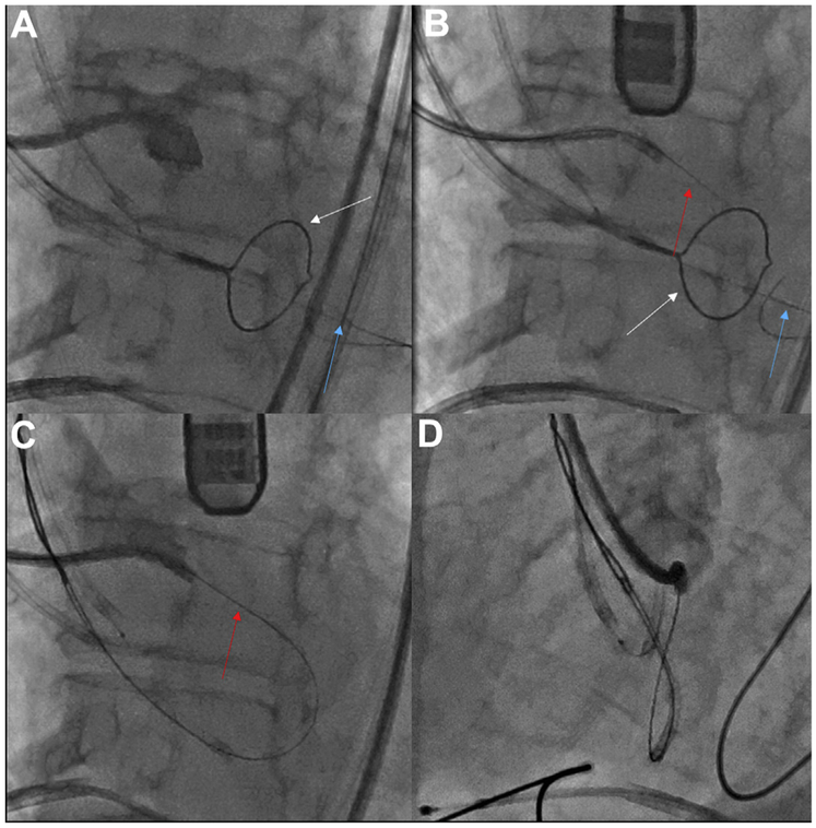
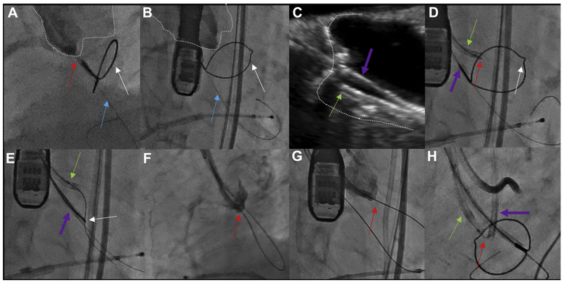
Coronary artery obstruction is an uncommon but devastating complication of transcatheter aortic valve replacement (TAVR). Computed tomography appears to be a sensitive but nonspecific predictor of coronary artery obstruction. Transcatheter approaches to prevent and treat coronary artery obstruction, such as "snorkel" stenting, are unsatisfactory because of serious early and late ischemic complications. Bioprosthetic or native aortic scallop intentional laceration to prevent iatrogenic coronary artery obstruction during TAVR (BASILICA) is an early-stage transcatheter procedure to prevent coronary artery obstruction. It works by splitting the native or bioprosthetic leaflets so that they splay after TAVR and preserve coronary artery inflow. Because of the paucity of suitable alternatives, there is interest in the BASILICA technique despite its infancy. This tutorial review summarizes current thinking about how to predict and prevent coronary artery obstruction using BASILICA. First, the authors depict the main pathophysiological mechanisms of TAVR-associated coronary artery obstruction, along with the factors thought to contribute to coronary obstruction. Next, the authors provide a step-by-step guide to analyzing pre-procedural computed tomographic findings to assess obstruction risk and, if desirable, to plan BASILICA. Next, the authors describe the mechanisms underlying transcatheter electrosurgery. Finally, they provide step-by-step guidance on how to perform the procedure, along with a required equipment list.

Keywords: cardiac computed tomography; coronary artery obstruction; transcatheter aortic valve replacement; transcatheter electrosurgery; valve-in-valve; virtual valve; virtual valve-to-coronary distance.


Figures

FIGURE 1
FIGURE 1. Define the Annular Plane
Mark the exact annular plane. This is an orthogonal side view (maximum intensity projection) confirming that the selected annular plane is accurate for this Magna-Ease valve. The dots on the annular nadirs (green, right coronary cusp [RC]; yellow, noncoronary cusp [NC]) overlap, and the stent posts overlap in this so-called 2:1 orientation. Left coronary artery origin is seen at 2 o’clock. Multiplanar reconstruction shows the center of rotation (3-pronged star). (Inset) example of annular plane selected for a Mitroflow bioprosthetic, which typically assumes a sigmoidal configuration after implantation; the plane should abut at the lowest 3 points. LC = left coronary cusp.
FIGURE 2
FIGURE 2. Expected Outer Diameter
The expected outer diameter of the intended transcatheter aortic valve replacement device is selected, considering the diameter of the waist (left) and the impact of constraint by the surgical valve such as flaring (right, arrows) of a SAPIEN 3. Reproduced with permission from Medtronic.
FIGURE 3
FIGURE 3. Virtual Valve Orientation
Virtual valve orientation. With the annular plane identified (A), a virtual valve cylinder is implanted and rotated (B,C) to align with the surgical valve posts and annular plane. Simultaneous short-axis reconstructions confirm alignment with the center of the annulus (D) and valve posts (E). It is important to factor the geometry and expected constraint on the surgical valve (F,G) in measurements of virtual valve-to-coronary distance.
FIGURE 4
FIGURE 4. Measure Virtual Valve-to-Coronary Distance and Virtual Valve-to-Sinotubular Junction Distance
The virtual valve-to-coronary (VTC) distance is measured in 2 orthogonal planes (top, axial; bottom, longitudinal). Representative VTC distance measurement for a right coronary artery (RCA) (A) and left coronary artery (LCA) (B). The valve-to-sinotubular junction (VTSTJ) distance is measured in orthogonal planes (C): axial (upper) and longitudinal (lower), when the sinotubular junction is lower than the height of the transcatheter aortic valve replacement device.
FIGURE 5
FIGURE 5. Projection Angles
Computed tomographic prediction of fluoroscopic projections. First the annular plane is defined by the 3 annular nadir points (red, left coronary cusp [LCC]; green, right coronary cusp [RCC]; yellow, noncoronary cusp), along with corresponding coronary ostia. (A) The side projection is selected along the annular plane so that the intended annular marker and coronary ostium are on the lateral aspect of the aortic root, and the contralateral annular markers are overlapping. (B) In en face projection, the annular marker and corresponding coronary ostium lie along the centerline of the aortic root, and the annular markers are evenly spaced in a “1-1-1” projection. If either of these projections is fluoroscopically unattainable, the craniocaudal angulation is reduced, while preserving the side or center alignment, until an attainable projection angle is obtained. (Bottom) Representative LCC projections (C to E and Online Video 1) and RCC projections (F to H and Online Video 2). (C,F) Optimal side views. (D,H) Optimal en face views. (E,G) Compromise projections with reduced craniocaudal.
FIGURE 6
FIGURE 6. Confounding Transcatheter Aortic Valve Replacement Device and Implantation Characteristics
Confounders from transcatheter aortic valve replacement (TAVR) device and implantation characteristics. (A to C) implantation characteristics including flaring, depth of implantation, and canting each significantly affect virtual valve-to-coronary (VTC) distance. (C to F) In vitro BASILICA TAVR inside a Mitroflow bioprosthetic valve using a SAPIEN 3 (D,E) and Evolut R (F,G). (D,F) TAVR device commissures are serendipitously aligned away from the laceration. (E,G) TAVR device commissures (red arrows) are aligned with the laceration and are more likely to obstruct coronary inflow. images courtesy of Danny Dvir. (H) Depiction of a SAPIEN aligning with a Mitroflow annulus and encroaching more on the left coronary artery (LCA). (I) In contrast, an Evolut R aligns with the ascending aorta and often orients away from the LCA.
FIGURE 7
FIGURE 7. Principles of Transcatheter Electrosurgery
(A) Charge (diffuse red cloud) will disperse around a kinked guidewire without (B) selective denudation of insultation from the inner-curve (“elbow”), which focuses charge (focal red cloud). (C) Even after focal denudation, blood ions will disperse charge. (D) Flooding the field with nonionic dextrose confines radiofrequency energy to the lacerating surface contacting the leaflet.
FIGURE 8
FIGURE 8. Left Coronary Cusp Traversal and Snare
Traversing the Left coronary cusp (LCC). (A) Side projection showing the LCC hinge point. (B) A sigmoid-shape coaxial crossing system combines a Long 5-F IM catheter inside a 7-F EBU guide catheter. The electrified Astato wire (red arrow) is traversing the leaflet, aimed at the left ventricular outflow tract (LVOT) snare (white arrow) stabilized by an anchor wire (blue arrow) in the left ventricular apex. (C,D) Angiography in side and en face projections, respectively, demonstrates that the traversal point is at the hinge point and midline (Online Video 3).
FIGURE 9
FIGURE 9. Right Coronary Cusp Traversal and Snare
Traversing the right coronary cusp (RCC) in native aortic valve disease. (A,B) Side and en face projections, respectively, with angiography through a RCC Judkins right guide directed at the traversal point. The aortic root is outlined. Red arrow indicates Astato wire; blue arrow indicates anchor wire to stabilize the snare; white arrow indicates left ventricular outflow tract (LVOT) snare. (C) Transesophageal echocardiography confirming orientation of the RCC guide (green arrow), which must be distinguished from the LVOT guide catheter (purple arrow). (D) Electrosurgical traversal. The Astato wire (red arrow) is crossing the target leaflet. (E) The Astato wire is snared via the LVOT catheter. (F,G) Angiography shows the Astato across the traversal point in the side and en face projections, respectively (H). The “flying V” configuration with the kinked and denuded Astato shaft (red arrow) straddling the leaflet. The piggyback tip is in position via the RCC guide. A left coronary cusp (LCC) guide and LVOT snare are in place for LCC traversal.
FIGURE 10
FIGURE 10. Flying V
Preparation of the “flying V” inner-surface denuded guidewire. (A) Two to three millimeters of guidewire is scraped noncircumferentially immediately distal to the locked Piggyback. (B) Using the back end of the scalpel, the guidewire is kinked against fingers behind a raised towel. (C) Noncircumferential inner-surface denudation (arrow) near the Piggyback in a “flying V” configuration.
FIGURE 11
FIGURE 11. Laceration
Laceration of 2 leaflets in sequence. (A) The kinked and denuded Astato (green arrow) across the right coronary cusp (RCC) is in a “flying V” configuration, with the adjoining Piggyback (white arrow). The Left coronary cusp (LCC) laceration system also is evident with a separate “flying V” (red arrow) and Piggyback (white arrow). (B) After RCC laceration, the transcatheter aortic vaLve repLacement guidewire (blue arrow) is positioned in the Left ventricLe, and then the LCC guidewire is electrified for laceration.
CENTRAL ILLUSTRATION
CENTRAL ILLUSTRATION. Mechanisms of Transcatheter Aortic Valve Replacement-Induced Coronary Obstruction and Mitigation by BASILICA
Mechanisms of transcatheter aortic valve replacement (TAVR)–induced coronary obstruction and mitigation by bioprosthetic or native aortic scallop intentional laceration to prevent iatrogenic coronary artery obstruction during TAVR (BASILICA). (A) In a deficient sinus of Valsalva, the outwardly displaced leaflets directly obstruct the coronary artery ostium. (B) In a low sinus of Valsalva and narrow sinotubular junction, the outwardly displaced leaflets indirectly obstruct the coronary artery ostium by sequestering the sinus. (C) A bulky leaflet mass can directly obstruct the coronary ostium. (D) In a low coronary ostium, the fabric-covered frame or skirt can directly obstruct the coronary artery ostium. (E) An electrified BASILICA guidewire lacerates the prior aortic valve leaflets. (F) A TAVR implant splays the lacerated leaflets and ensures inflow to the threatened coronary ostium after BASILICA.

References

    1. Ribeiro HB, Nombela-Franco L, Urena M, et al. Coronary obstruction following transcatheter aortic valve implantation: a systematic review. J Am Coll Cardiol Intv 2013;6:452–61. - PubMed
    1. Ribeiro HB, Webb JG, Makkar RR, et al. Predictive factors, management, and clinical outcomes of coronary obstruction following transcatheter aortic valve implantation: insights from a large multicenter registry. J Am Coll Cardiol 2013;62:1552–62. - PubMed
    1. Dvir D, Leipsic J, Blanke P, et al. Coronary obstruction in transcatheter aortic valve-in-valve implantation: preprocedural evaluation, device selection, protection, and treatment. Circ Cardiovasc Interv 2015;8:e002079. - PubMed
    1. Ribeiro HB, Rodes-Cabau J, Blanke P, et al. Incidence, predictors, and clinical outcomes of coronary obstruction following transcatheter aortic valve replacement for degenerative bioprosthetic surgical valves: insights from the VIVID registry. Eur Heart J 2018;39:687–95. - PubMed
    1. Jabbour RJ, Tanaka A, Finkelstein A, et al. Delayed coronary obstruction after transcatheter aortic valve replacement. J Am Coll Cardiol 2018;71:1513–24. - PubMed

MeSH terms