

Bacterial Density and Biofilm Structure Determined by Optical Coherence Tomography
- PMID: 31278369
- PMCID: PMC6611762
- DOI: 10.1038/s41598-019-46196-7
Bacterial Density and Biofilm Structure Determined by Optical Coherence Tomography
Abstract
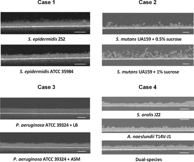
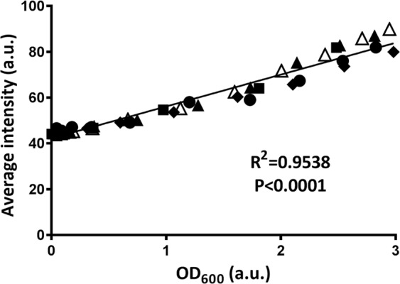
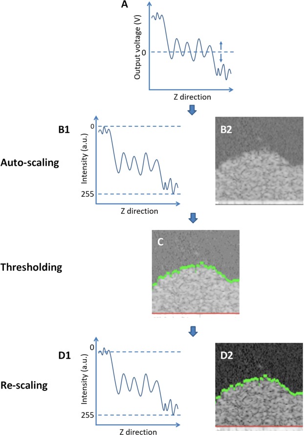
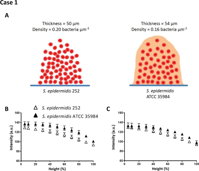
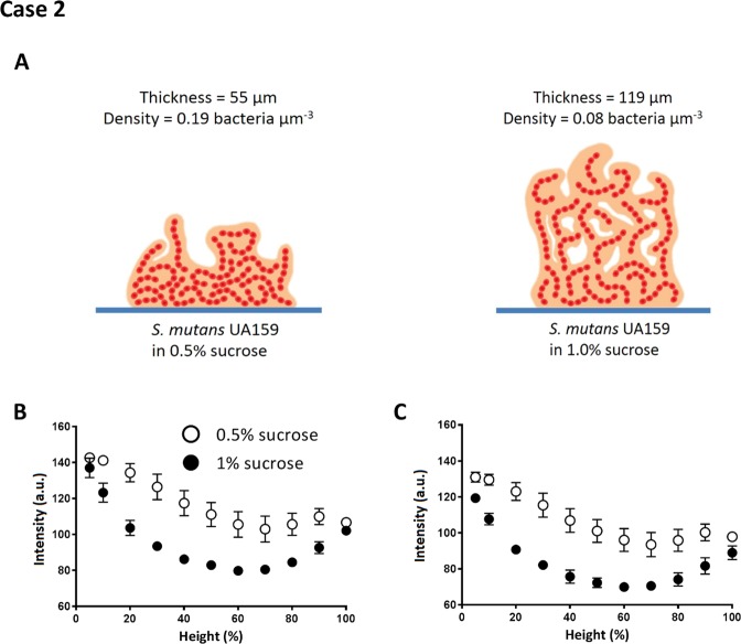
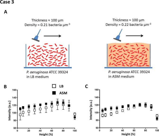
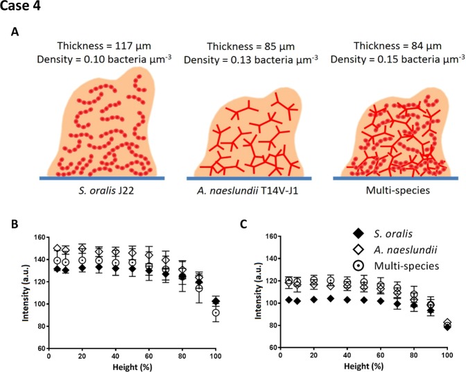
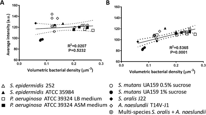
Optical-coherence-tomography (OCT) is a non-destructive tool for biofilm imaging, not requiring staining, and used to measure biofilm thickness and putative comparison of biofilm structure based on signal intensity distributions in OCT-images. Quantitative comparison of biofilm signal intensities in OCT-images, is difficult due to the auto-scaling applied in OCT-instruments to ensure optimal quality of individual images. Here, we developed a method to eliminate the influence of auto-scaling in order to allow quantitative comparison of biofilm densities in different images. Auto- and re-scaled signal intensities could be qualitatively interpreted in line with biofilm characteristics for single and multi-species biofilms of different strains and species (cocci and rod-shaped organisms), demonstrating qualitative validity of auto- and re-scaling analyses. However, specific features of pseudomonas and oral multi-species biofilms were more prominently expressed after re-scaling. Quantitative validation was obtained by relating average auto- and re-scaled signal intensities across biofilm images with volumetric-bacterial-densities in biofilms, independently obtained using enumeration of bacterial numbers per unit biofilm volume. The signal intensities in auto-scaled biofilm images did not significantly relate with volumetric-bacterial-densities, whereas re-scaled intensities in images of biofilms of widely different strains and species increased linearly with independently determined volumetric-bacterial-densities in the biofilms. Herewith, the proposed re-scaling of signal intensity distributions in OCT-images significantly enhances the possibilities of biofilm imaging using OCT.
Conflict of interest statement
H.J.B. is also director of a consulting company SASA BV. The authors declare no potential conflicts of interest with respect to authorship and/or publication of this article. Opinions and assertions contained herein are those of the authors and are not construed as necessarily representing views of the funding organization or their respective employers. We declare no competing financial interest.
Figures
Similar articles
-
Investigation of the mesoscale structure and volumetric features of biofilms using optical coherence tomography.Biotechnol Bioeng. 2010 Dec 1;107(5):844-53. doi: 10.1002/bit.22864. Biotechnol Bioeng. 2010. PMID: 20717977
-
Optical coherence tomography in biofilm research: A comprehensive review.Biotechnol Bioeng. 2017 Jul;114(7):1386-1402. doi: 10.1002/bit.26283. Epub 2017 Mar 23. Biotechnol Bioeng. 2017. PMID: 28266013 Review.
-
Assessing the influence of biofilm surface roughness on mass transfer by combining optical coherence tomography and two-dimensional modeling.Biotechnol Bioeng. 2016 May;113(5):989-1000. doi: 10.1002/bit.25868. Epub 2015 Nov 10. Biotechnol Bioeng. 2016. PMID: 26498328
-
Investigating biofilm structure developing on carriers from lab-scale moving bed biofilm reactors based on light microscopy and optical coherence tomography.Bioresour Technol. 2016 Jan;200:128-36. doi: 10.1016/j.biortech.2015.10.013. Epub 2015 Oct 13. Bioresour Technol. 2016. PMID: 26476614
-
Physico-chemistry of bacterial transmission versus adhesion.Adv Colloid Interface Sci. 2017 Dec;250:15-24. doi: 10.1016/j.cis.2017.11.002. Epub 2017 Nov 5. Adv Colloid Interface Sci. 2017. PMID: 29129313 Review.
Cited by
-
Chemical and mechanical influence of root canal irrigation on biofilm removal from lateral morphological features of simulated root canals, dentine discs and dentinal tubules.Int Endod J. 2021 Jan;54(1):112-129. doi: 10.1111/iej.13399. Epub 2020 Nov 19. Int Endod J. 2021. PMID: 32880989 Free PMC article.
-
Assessment of the Antibiofilm Performance of Chitosan-Based Surfaces in Marine Environments.Int J Mol Sci. 2022 Nov 24;23(23):14647. doi: 10.3390/ijms232314647. Int J Mol Sci. 2022. PMID: 36498973 Free PMC article.
-
Biomass-specific rates as key performance indicators: A nitrogen balancing method for biofilm-based electrochemical conversion.Front Bioeng Biotechnol. 2023 Jan 19;11:1096086. doi: 10.3389/fbioe.2023.1096086. eCollection 2023. Front Bioeng Biotechnol. 2023. PMID: 36741763 Free PMC article.
-
Periodic chemical cleaning with urea: disintegration of biofilms and reduction of key biofilm-forming bacteria from reverse osmosis membranes.Water Res X. 2021 Aug 26;13:100117. doi: 10.1016/j.wroa.2021.100117. eCollection 2021 Dec 1. Water Res X. 2021. PMID: 34585132 Free PMC article.
-
Mass transfer in heterogeneous biofilms: Key issues in biofilm reactors and AI-driven performance prediction.Environ Sci Ecotechnol. 2024 Aug 29;22:100480. doi: 10.1016/j.ese.2024.100480. eCollection 2024 Nov. Environ Sci Ecotechnol. 2024. PMID: 39309319 Free PMC article. Review.
References
Publication types
MeSH terms
LinkOut - more resources
Full Text Sources
Molecular Biology Databases
