. 2019 Aug 7;19(15):2537-2548.
doi: 10.1039/c9lc00400a. Epub 2019 Jul 10.

Clinical translation of microfluidic sensor devices: focus on calibration and analytical robustness

Affiliations

Clinical translation of microfluidic sensor devices: focus on calibration and analytical robustness

Sally A N Gowers et al. Lab Chip. .

Abstract

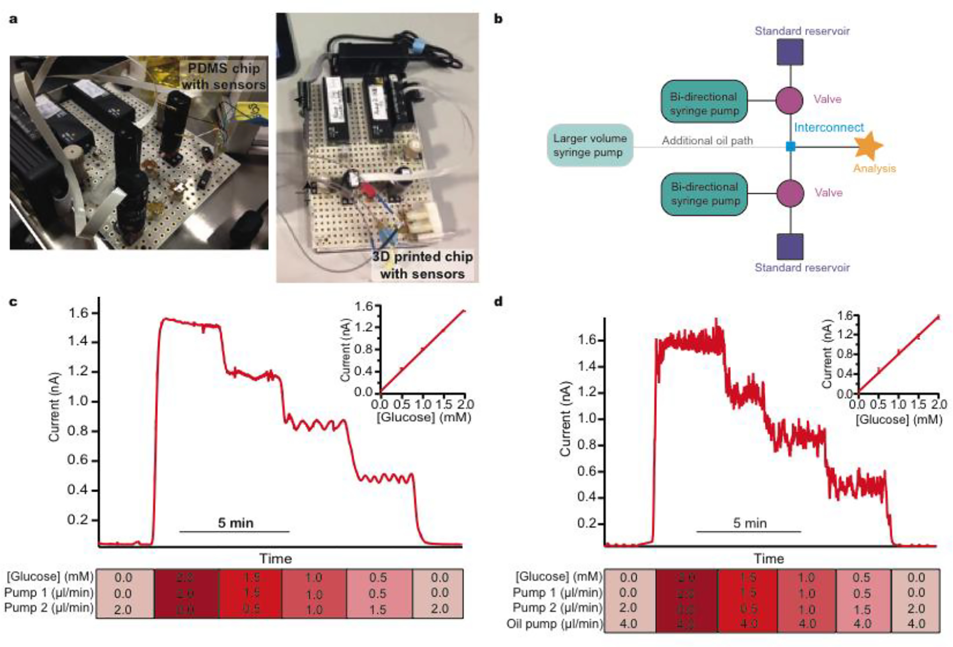
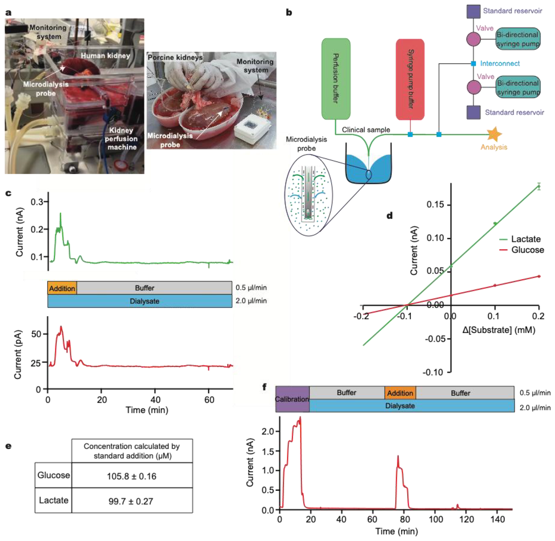
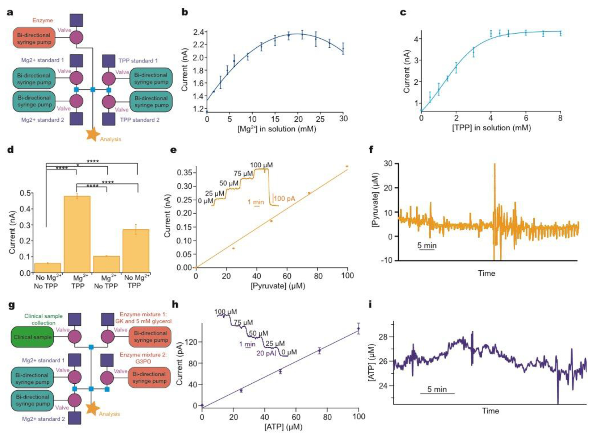
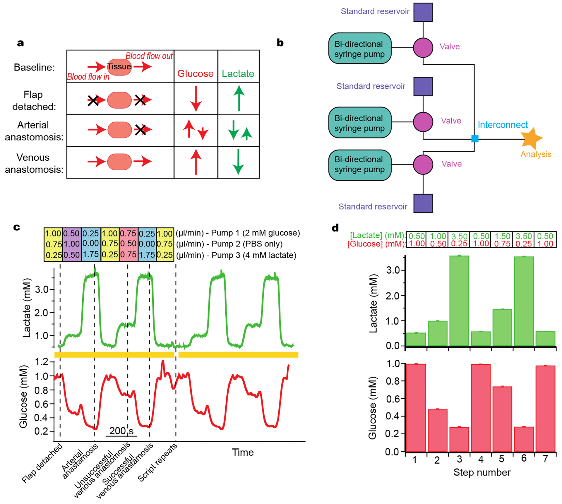
We present approaches to facilitate the use of microfluidics outside of the laboratory, in our case within a clinical setting and monitoring from human subjects, where the complexity of microfluidic devices requires high skill and expertise and would otherwise limit translation. Microfluidic devices show great potential for converting complex laboratory protocols into on-chip processes. We demonstrate a flexible microfluidic platform can be coupled to microfluidic biosensors and used in conjunction with clinical microdialysis. The versatility is demonstrated through a series of examples of increasing complexity including analytical processes relevant to a clinical environment such as automatic calibration, standard addition, and more general processes including system optimisation, reagent addition and homogenous enzyme reactions. The precision and control offered by this set-up enables the use of microfluidics by non-experts in clinical settings, increasing uptake and usage in real-world scenarios. We demonstrate how this type of system is helpful in guiding physicians in real-time clinical decision-making.


Figures

Figure 1:
Figure 1:
Simple modular microfluidic module arrangements for continuous and droplet-based basic calibration systems a: Photographs of the LabSmith® devices connected to either a PDMS sensor chip or a 3D-printed sensor chip. B: Schematic of basic calibration layout consisting of a bidirectional syringe pump connected to a three-port two-position valve and reservoir. When the valve is switched towards the reservoir the pump can be programmed to pull solution quickly from the reservoir to refill the syringe. The valve can then be switched towards the analysis chip and programmed to slowly dispense solution at a precisely controlled flow rate. A larger external pump (shown in green) can be connected into the system to deliver an oil phase and create droplets at the interconnect (shown in blue). c: Continuous calibration at constant 2.0 μl/min total flow rate. Standard 1 is 0.0 mM glucose and standard 2 is 2.0 mM glucose. Each step change is 0.5 mM. The final glucose concentration and flow rates of each pump are shown for each step below the calibration data. d: Droplet calibration. Total aqueous flow rate 2.0 μl/min. Oil flow rate 4.0 μl/min. Standard 1 is 0.0 mM glucose and standard 2 is 2.0 mM glucose. Each step change is 0.5 mM. The final glucose concentration and flow rates of each pump are shown for each step below the calibration data.
Figure 2:
Figure 2:
Clinical system to monitor TBI patients in ITU a: Schematic of microfluidic platform layout. b: Top photograph shows an electrocorticography strip electrode (ECoG), the microdialysis probe and the intracranial pressure (ICP) probe which are inserted into human brain tissue during a craniotomy. Bottom photograph depicts use in King’s College Hospital ITU. The dotted blue line shows where a length of fine-bore tubing connects the implanted microdialysis probe to the analysis system. c: An example potassium calibration carried out during TBI monitoring in the hospital. Dialysate measurements are indicated by blue bars and multi-point calibration by purple bars. Concentrations are 10.0, 2.70, 6.35 and 10.0 mM (levels indicated by dotted lines). This is an expanded view of the calibration highlighted by a yellow box in (e). d: Removal of air bubble in chip using the larger capacity flow module. An air bubble caused a sudden decrease in the signal-to-noise ratio of a sample perfused at 2 μl/min. PBS was flushed through the system at 10 μl/min on top of the glucose flow for 20 seconds, removing the air bubble and the signal returned to the same level. e: Clinical automatic calibration example in TBI patient monitoring. Potassium (purple), glucose (red) and lactate (green) sensors were continually analysing dialysate (blue boxes) in between programmed calibration cycles (purple boxes). Known standards were introduced every 3 h (glucose: 0.0, 2.0, 1.0 mM, lactate: 1.0, 0.0, 0.5 mM, potassium: 10.0, 2.70, 6.35 mM). The changes in potassium and lactate seen at around 3 h are not artefactual but possibly represent a pathophysiological event that is not picked up by other monitoring modalities.
Figure 3:
Figure 3:
Standard addition to calibrate sensors during human and porcine kidney monitoring a: A photograph of human kidney microdialysis monitoring during reperfusion and of online monitoring of porcine kidneys at the abattoir b: Schematic of the instrumentation layout used in human and porcine studies. Larger external pumps for continuous buffer delivery and the addition of the clinical sample were used in conjunction with the calibration setup previously described. Inset: schematic showing exchange of analytes across microdialysis membrane. c: Initially, standard addition was run by adding a 3-point calibration (0.2, 0.1 and 0.0 mM) of glucose (red) and lactate (green) to the clinical sample stream. Analyte concentrations were chosen so that when they are diluted by the sample stream the final concentrations covered the appropriate physiological range. The dialysate was then measured. d: Current versus change in concentration for standard addition of glucose (red) and lactate (green). Extrapolation to where the lines cross the x-axis gives the sample concentration in the final volume. e: Concentrations for glucose and lactate calculated using standard addition, corresponding to a recovery of approx. 25%. f: Dialysate glucose levels in an ex vivo porcine kidney during cold preservation. A 5-point glucose calibration was carried out (steps: 0.00, 1.25, 2.50, 3.75 and 5.00 mM) at 2.5 μl/min, after which the dialysate was analysed. Midway through, a 3-point standard addition equivalent to 0.00, 0.625 and 1.25 mM glucose in the final solution was carried out.
Figure 4:
Figure 4:
Addressing system problems: optimisation and reaction cascades a: Schematic of modular platform to individually optimise cofactor concentration for pyruvate detection, comprising two sets of basic layouts with an additional module for enzyme addition (pink). b: The concentration of Mg2+ was varied and the current recorded for 0.5 mM pyruvate and 0.9 mM TPP. c: The concentration of TPP was varied and the current recorded for 0.5 mM pyruvate and 16.8 mM Mg2+. d: Significant improvement of current response following addition of optimised cofactors for 0.5 mM pyruvate. Tested using Mann-Whitney U Test. Significance: * p<0.05 and **** p<0.0001. e: 5-point pyruvate calibration at 2 μL/min in physiological range dosing in POx (30 mg/ml, 0.5 μl/min) and optimised cofactor concentrations. Markers represent mean ± standard deviation and are fitted with a straight line. Inset shows raw data for the 5-point pyruvate calibration. f: Raw data excerpt for dialysate brain pyruvate levels in a TBI patient at King’s College Hospital. g: Schematic of the modular platform to sequentially dose in two enzyme mixtures, illustrated for ATP detection. Adaptation from the basic calibration layout is shown in pink (enzyme additions) and green (clinical sample). h: 5-point ATP calibration in physiological range at 2 μL/min, consecutively dosing in glycerol (5 mM) and glycerokinase (GK, 6.25 mg/ml, 0.5 μl/min), and glycerol-3-phosphate oxidase (G3PO, 6.55 mg/ml, 0.5 μl/min). Markers represent mean ± standard deviation and are fitted with a straight line. Inset: raw data for the 5-point ATP concentration. i: ATP levels in kidney dialysate, collected in storage tubin before analysis.
Figure 5:
Figure 5:
Simulation of free flap surgery for system optimization a: Schematic of the various stages of free flap surgery and the relative magnitude and direction of corresponding typical changes in glucose and lactate. b: Schematic of the layout used. c: Lactate (green) and glucose (red) response during a computer-controlled automatic simulation of typical metabolite changes during free flap surgery. Dotted lines indicate surgical events that these levels typically correspond to. The simulation script was set to automatically repeat; yellow bars indicate two complete script cycles given as an example. The respective flow rates for each flow module are given above the trace. Pump 1 contained 2 mM glucose and 0 mM lactate, pump 2 contained 0 mM glucose and 0 mM lactate, and pump 3 contained 0 mM glucose and 4 mM lactate. d: Histograms of glucose and lactate concentrations detected for each step of simulation over 4 repeats. Histograms show mean ± standard deviation. Input concentrations are indicated above the histograms for each step for lactate in green and for glucose in red.

References

    1. Chen C, Mehl BT, Munshi AS, Townsend AD, Spence M and Martin RS, Anal. Methods, 2017, 8, 6005–6012. - PMC - PubMed
    1. Shang L, Cheng Y and Zhao Y, Chem. Rev, 2017, 117, 7964–8040. - PubMed
    1. Gong MM and Sinton D, Chem. Rev, 2017, 117, 8447–8480. - PubMed
    1. Han KN, Li CA and Seong GH, Annu. Rev. Anal. Chem, 2013, 6, 119–141. - PubMed
    1. Nge PN, Rogers CI and Woolley AT, Chem. Rev, 2013, 113, 2550–2583. - PMC - PubMed

Publication types

MeSH terms

Substances