Review
. 2019 May 9;10(22):5656-5666.
doi: 10.1039/c9sc01662g. eCollection 2019 Jun 14.

Energy storage: pseudocapacitance in prospect

Affiliations
Review

Energy storage: pseudocapacitance in prospect

Cyrille Costentin et al. Chem Sci. .

Abstract

The two main types of charge storage devices - batteries and double layer charging capacitors - can be unambiguously distinguished from one another by the shape and scan rate dependence of their cyclic voltammetric current-potential (CV) responses. This is not the case with "pseudocapacitors" and with the notion of "pseudocapacitance", as originally put forward by Conway et al. After insisting on the necessity of precisely defining "pseudocapacitance" as involving faradaic processes and having, at the same time, a capacitive signature, we discuss the modelling of "pseudocapacitive" responses, revisiting Conway's derivations and analysing critically the other contributions to the subject, leading unmistakably to the conclusion that "pseudocapacitors" are actually true capacitors and that "pseudocapacitance" is a basically incorrect notion. Taking cobalt oxide films as a tutorial example, we describe the way in which a (true) electrical double layer is built upon oxidation of the film in its insulating state up to an ohmic conducting state. The lessons drawn at this occasion are used to re-examine the classical oxides, RuO2, MnO2, TiO2, Nb2O5 and other examples of putative "pseudocapacitive" materials. Addressing the dynamics of charge storage-a key issue in the practice of power of the energy storage device-it is shown that ohmic potential drop in the pores is the governing factor rather than counter-ion diffusion as often asserted, based on incorrect diagnosis by means of scan rate variations in CV studies.


Figures
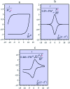
Fig. 1
Fig. 1. Cyclic voltammetric current–potential responses. i: current, E: electrode potential, E0: standard potential of the surface or solution redox couple, ν: scan rate, S: electrode surface area, F: Faraday, T: absolute temperature. (a) Double layer charging current (Cd: double layer differential capacitance). (b) Faradaic response of a surface redox couple (Γm: surface concentration, E0: standard potential of the surface redox couple). (c) Faradaic response of a solution redox couple (C0: solution concentration, E0: standard potential of the surface redox couple, D: reactant diffusion coefficient).
Fig. 2
Fig. 2. C φ vs. electrode potential profiles for an electrosorption process involving a zero (blue) and a positive (red) g value, i.e., for lateral repulsion. Adapted from Fig. 10.1 in ref. 10 p. 228, with permission.
Fig. 3
Fig. 3. Cyclic voltammograms for the redox couple giving rise to pseudocapacitance: (a) free in solution (diffusion controlled) compared with surface bound; (b) experimental example of ferrocyanide bound on poly(vinylpyridine) (from Conway and Duic, unpublished). Adapted from Fig. 10.14 in ref. 10 pp. 250 and 251, with permission.
Fig. 4
Fig. 4. Formal capacitance Cφvs. electrode potential as a function of the parameter 2(aQ + aP – 2aPQ) = FΔE0/RT = 0.1 (blue), 1 (red), 2 (green), 3 (yellow), 4 (gray), and 5 (magenta). (a) Calculated from interaction coefficients, aP, aQ and aPQ linearly varying with the surface concentrations. (b) Calculated from the square standard potential distribution.
Fig. 5
Fig. 5. Cyclic voltammetry current–potential responses (potential: 1.29 → 0.59 → 1.59 → 1.29 V vs. SHE) at 8 V s–1 of a 39 nm cobalt oxide deposited (CoPi) film in the presence of 0.2 M potassium phosphate (KPi) at pH = 7. Adapted from Fig. 2 in ref. 18 with permission.
Fig. 6
Fig. 6. Cyclic voltammetry current–potential responses at various scan rates (ν) of CoPi films at pH 7 in the presence of 1 mM Pi and 100 mM KNO3. ν (V s–1): 1 (red), 2 (orange), 3 (black), 4 (green), 5 (cyan), 6 (gray), 7 (magenta), and 8 (blue). The numbers on each diagram are the values of film thickness in nm and, between parentheses, the value of the plateau capacitance in μF cm–2. Adapted from ref. 18, with permission.
Fig. 7
Fig. 7. (a) CV of a 39 nm CoPi film in 1 mM KPi, pH = 7, and 100 mM KNO3. Scans are initiated at 1.29 V vs. SHE in the cathodic direction and inversion potential is varying. ν = 2 V s–1. (b) CV of a 39 nm CoPi film in the presence of 100 mM KNO3 and 1 mM KPi, pH 7. Scans are initiated at 1.29 V vs. SHE in the cathodic direction. ν = 2 V s–1. Films were deposited from different buffers: 100 mM KPi, pH 7 (black), 100 mM KHCO3, pH 10.3 (red), 100 mM KBi (blue), pH 9.2 (dots).
Fig. 8
Fig. 8. (a) Structural sketch of cobalt oxide electrodeposited films. (b) Scheme of the various phases considered in the electrochemical description of a cobalt oxide electrodeposited. Adapted from Fig. 4 in ref. 18 with permission.
Fig. 9
Fig. 9. (a) Forward CV scan for with Cd = 2.55 mF cm–2 (i.e. capacitance of a 40 nm CoPi film), F2N/RT = 20 mF cm–2 (i.e. N = 8 × 1020 cm–3 for a 40 nm film), E0,ap – ΔE0/2 + φS = 0.5 V (dashed vertical line), T = 298 K. (b) Evolution of the film inner potential. Adapted from Fig. 5 in ref. 19 with permission.
Fig. 10
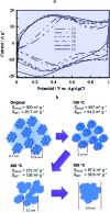
Fig. 10. 0(a) CV curves of (1) pristine RuOx·nH2O and RuOx·nH2O annealed in air for 2 h at (2) 150, (3) 200, (5) 350 and (6) 400 °C. CV curves were measured in 0.1 M H2SO4 at 25 mV s–1 from ref. 29 with permission. (b) Schematic diagram of the hierarchical nanostructure in RuOx·nH2O changing with the annealing temperature from ref. 32 with permission.
Fig. 11
Fig. 11. The electrochemical double layer.
Fig. 12
Fig. 12. Top: Schematic representation of a bi-hierarchical structure of a porous electrode film with nanopores and mesopores; h = mesopores average size, λD: Debye screening distance (of the order of 1–10 nm). Bottom: Transmission line model applied to mesopores. φsubscript: potentials, i: current flowing through the film, distributed resistance and capacitance parameters of the equivalent transmission line: ρP: resistivity of the ionic solution, γP: fraction of the base electrode covered by the pore ends, Ru: resistance of the solution, c: capacitance per unit volume of the film, x: distance from the base electrode, df: thickness of the film.
Fig. 13
Fig. 13. Variation of the dimensionless current function with (a) the dimensionless potential, (EEi)/(EfEi) for several values of the parameter tf/tv = 0.1 (blue), 0.5 (green), 2 (grey), and 20 (red), with negligible solution resistance Ru = 0; (b) with the dimensionless time t/tf, with tf/tv = 0.5 and Ru = 0 (blue line). The green line is the limiting behaviour observed at short times.
Fig. 14
Fig. 14. Variations of the capacitance with scan rate from MnO2 electrodes in ref. 69 (from multicycle limiting CV responses). (a) Amorphous, (b) birnessite, (c) spinel, in aqueous Li2SO4 (red) and (NMe4)2SO4 (blue). Data points: closed circles. Full lines: fitting of data by means of a transmission line model. Dotted lines: simulations with a RC model (see ref. 68 for details).

References

    1. Winter M., Brodd R. J. Chem. Rev. 2004;104:4245–4269. - PubMed
    1. Note that in some cases, the species that cross the interfacial potential drop is an ion rather than an electron. See for example: White H. S., Peterson J. D., Cui Q., Stevenson K. J., J. Phys. Chem. B, 1998, 102 , 2930 –2934 .
    1. Note that we use here the term ‘double layer’ for electrochemical capacitive processes although the classical Gouy–Chapman–Stern double layer model (see ref. 4) applies for planar electrodes. More complex models may have to be considered for porous electrodes

    1. Delahay P., Double Layer and Electrode Kinetics, Wiley, New York, 1955, ch. 7.
    1. Savéant J.-M., Elements of molecular and biomolecular electrochemistry: an electrochemical approach to electron transfer chemistry, John Wiley & Sons, Hoboken, NJ, 2006.