doi: 10.5935/abc.20190106.
Vascular Ultrasound Statement from the Department of Cardiovascular Imaging of the Brazilian Society of Cardiology - 2019
[Article in
English,
Portuguese]
Affiliations
- PMID: 31314836
- PMCID: PMC6636370
- DOI: 10.5935/abc.20190106
Item in Clipboard
Vascular Ultrasound Statement from the Department of Cardiovascular Imaging of the Brazilian Society of Cardiology - 2019
[Article in
English,
Portuguese]
Arq Bras Cardiol.
.
No abstract available
Figures

Schematic illustration showing examples of IMT and plaque
measurements. IMT measurement (A). Different measurements of 3
carotid plaques: encroaching ≥ 0.5 mm on the arterial lumen
(B); measurement > 50% of the surrounding IMT value (C); large
plaque (D).

Right carotid and its anatomical subdivisions recommended by the
group (adapted from the Mannheim study).9 CC: common carotid; IB:
internal branch; BCA: brachiocephalic artery.

Recommendation from the Department of Cardiovascular Imaging of
the Brazilian Society of Cardiology for the sequence of
evaluation of carotid stenosis. PSV: peak systolic velocity.

Normal flow patterns of carotid arteries. (A) Common carotid
artery. (B) Internal carotid artery. (C) External carotid
artery.
(1) Diagram illustrating the placement of the cursor and the
insonation angle. (A) Parallel to the jet in case of
stenosis. (B) Parallel to the vessel. (2) Cursor and
insonation angle toward the flow jet in case of stenosis
(arrow).

Measurement of lumen reduction. (A) Smooth atheromatous
plaque in the lumen. (B) Irregular atheromatous plaque in
the lumen.
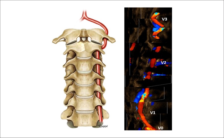
Extracranial segments of the vertebral artery (V0-V3).
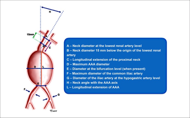
Preoperative assessment of abdominal aortic aneurysm (AAA).

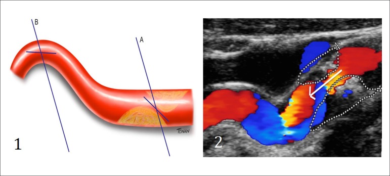
Color flow imaging showing the flow proximal to the lesion in
red and the turbulent flow at the lesion site (arrow). The
diagrams A and C demonstrate the velocity spectrum with
Doppler. (A) Cursor proximal to the lesion to measure V1.
(B) Cursor at the lesion site to measure V2. (C) Cursor
distal to the lesion with damped waveform.
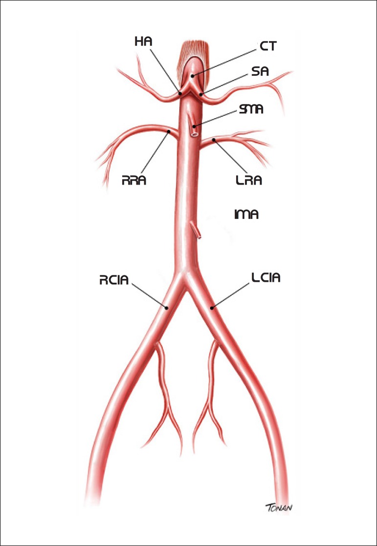
Abdominal aorta and branches. SA: splenic artery; HA: hepatic
artery; RCIA: right common iliac artery; LCIA: left common iliac
artery; IMA: inferior mesenteric artery; RRA: right renal
artery; LRA: left renal artery; SMA: superior mesenteric artery;
CT: celiac trunk.

Mesenteric vessels and abdominal aorta. (A) Transverse plane with
B-scan showing the superior mesenteric artery (SMA) anteriorly
and the abdominal aorta (AA) posteriorly. (B) Longitudinal plane
of the abdominal aorta and emergence of the celiac trunk and
SMA.
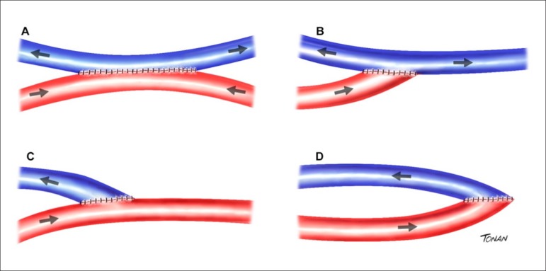
Types of brachiocephalic fistulas (Brescia-Cimino). (A)
Latero-lateral between artery and vein. (B) Terminal artery –
lateral vein. (C) Terminal vein – lateral artery. (D)
Termino-terminal between artery and vein.

Types of polytetrafluoroethylene (PTFE) grafts. (A) Straight PTFE
graft between the basilic vein and radial artery. (B) Loop PTFE
graft between the basilic vein and radial artery. (C) Curved PTFE
graft between the brachial artery and vein. (D) Loop PTFE graft
between the great saphenous vein and femoral artery.

Measurement of the distance between the brachial artery and
basilic vein before the creation of alternative arteriovenous
fistulas.

Steal phenomenon with retrograde flow in the radial artery (in
blue), in the segment distal to the anastomosis of arteriovenous
fistulas for hemodialysis.

Two-dimensional image of a recent partial thrombus (acute) located in
the valve sinus of the common femoral vein, shown through
longitudinal (A) and transverse (B) planes. There is no complete
collapse of the vein during compression (C).

Venous compression maneuver. (A) Artery and vein without
compression. (B) Normal vein with total compression. (C) Dilated
and incompressible vein, with recent thrombus. (D)
Incompressible vein, with old thrombus (chronic). (E)
Rethrombosis.
References
-
- Freire CM, Alcântara ML, Santos SN, Amaral SI, Veloso O, Porto CLL, et al. Recomendações para quantificação pelo US da doença aterosclerótica das artérias carótidas e vertebrais: grupo de trabalho do departamento de imagem cardiovascular da Sociedade Brasileira de Cardiologia - DIC - SBC. Arq Bras Cardiol: Imagem cardiovasc. 2015;28(número especial):e1–64.
-
- Alcântara ML, Santos SN, Freire CM, Amaral SI, Veloso O, Porto CL, et al. Recomendações para avaliação ultrassonográfica da aorta abdominal e ramos: grupo de trabalho do departamento de imagem cardiovascular da Sociedade Brasileira de Cardiologia - DIC - SBC. Arq Bras Cardiol: Imagem cardiovasc. 2016;29(nº especial):e1–68.
-
- Grant EG, Benson CB, Moneta GL, Alexandrov AV, Baker JD, Bluth EI, et al. Carotid artery stenosis: gray-scale and Doppler US diagnosis--Society of Radiologists in Ultrasound Consensus Conference. Radiology. 2003;229(2):340–346. - PubMed
-
- Oates CP, Naylor AR, Hartshorne T, Charles SM, Fail T, Humphries K, et al. Joint recommendations for reporting carotid ultrasound investigations in the United Kingdom. Eur J Vasc Endovasc Surg. 2009;37(3):251–261. - PubMed
-
- World Health Organization Noncommunicable diseases. [2018 Jun 1]. Available in: http://www.who.int/mediacentre/factsheets/fs355/en.
MeSH terms
LinkOut - more resources
Full Text Sources