. 2019 Aug;80(4):338-351.
doi: 10.1055/s-0038-1675174. Epub 2018 Oct 9.

Anatomical Step-by-Step Dissection of Complex Skull Base Approaches for Trainees: Surgical Anatomy of the Posterior Petrosal Approach

Affiliations

Anatomical Step-by-Step Dissection of Complex Skull Base Approaches for Trainees: Surgical Anatomy of the Posterior Petrosal Approach

Christopher S Graffeo et al. J Neurol Surg B Skull Base. 2019 Aug.

Abstract

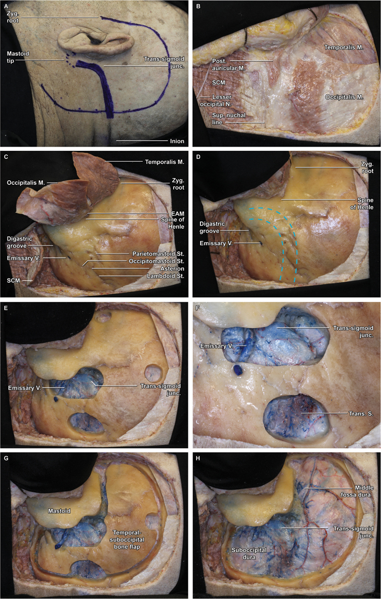
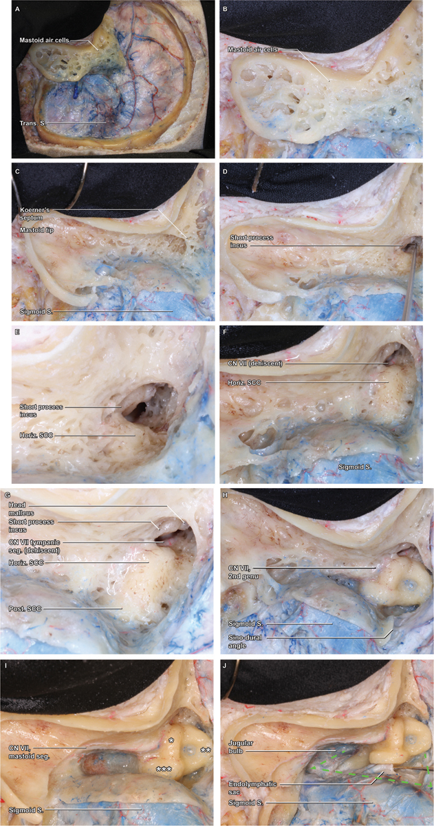
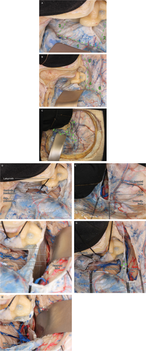
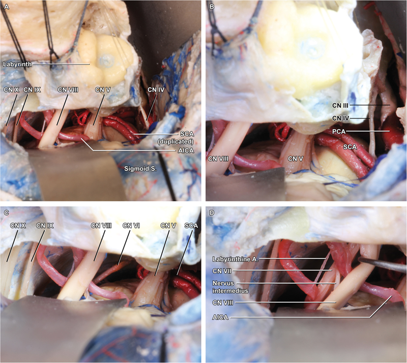
Introduction Although numerous anatomical and operative atlases have been published, those that have focused on the skull base either have provided views that are quite difficult to achieve in the operating room to better depict surgical anatomy or are written at the level of an audience with considerable knowledge and experience. Methods Five sides of three formalin-fixed latex-injected specimens were dissected under microscopic magnification. A posterior petrosectomy approach was performed by three neurosurgical residents at different training levels with limited previous experience in anatomical dissection mentored by the senior authors (C. L. W. D. and M. J. L.) and a clinical skull base fellow with additional anatomical dissection experience (M. P. C.). Anatomical dissections were performed until the expected level of dissection quality was achieved to demonstrate each important step of the surgical approach that would be understandable to all trainees of all levels. Following dissection education, representative case applications were reviewed. Results The posterior petrosectomy (also known as presigmoid retrolabyrinthine approach) affords excellent access to cranial nerves III to XI and a diverse array of pathologies. Key steps include positioning and skin incision, scalp and muscle flaps, burr holes, craniotomy flap elevation, superficial mastoidectomy, otic capsule exposure and presigmoid dura decompression, primary presigmoid durotomy, inferior temporal durotomy, superior petrosal sinus ligation, tentorium sectioning, and final exposure. Conclusion The posterior petrosectomy is a challenging approach; thorough operative-style laboratory dissection is essential to provide trainees with a suitable guide. We describe a comprehensive approach to learning this technique, intended to be understandable and usable by a resident audience.

Keywords: brainstem; education; meningioma; posterior petrosectomy; skull base.


Conflict of interest statement

Conflict of Interest None.

Figures

Fig. 1
Fig. 1
Step-by-step combined posterior petrosectomy approach in an anatomical specimen (left side). ( A ) Marked skin incision 1 cm anterior to the tragus, 6 to 8 cm superior to the pinna, and 6 cm posterior to the pinna. The transverse sinus is approximated by connecting an imaginary line between the inion and a point just above the root of the ipsilateral zygoma, whereas the sigmoid sinus is projected along the digastric groove. ( B ) The scalp flap is reflected anteriorly and secured in place with fishhooks, revealing the underlying musculature, including temporalis, occipitalis, posterior auricular, and sternocleidomastoid (SCM) muscles. ( C ) Overview demonstrating the myopericranial flaps: temporalis anteriorly, SCM and nuchal musculature inferiorly, and occipitalis laterally. ( D ). Overview of relationships between superficial bony landmarks and underlying dural venous sinuses (dashed blue lines), which are best approximated by a line from the zygomatic root to the inion for the transverse sinus and by the digastric groove for the sigmoid sinus. ( E ) Four burr holes are fashioned: at the zygomatic root, at the superior aspect of the exposure just below the superior temporal line, directly spanning the proximal transverse sinus, and overriding the transverse–sigmoid junction and sigmoid sinus. ( F ) Detail view of the inferior burr holes demonstrating the exposure of the transverse–sigmoid junction, as well as a large emissary vein. ( G ) The suprainfratentorial bone flap is seen in place following the craniotomy and prior to elevation. ( H ) Removal of the craniotomy flap widely exposes the underlying dura of the temporal lobe and posterior fossa.
Fig. 2
Fig. 2
Mastoidectomy. ( A ) With the craniotomy flap removed, attention can be turned to the mastoidectomy, which is initiated by removal of the superficial cortex with a large cutting burr. ( B ) A detail view demonstrates the thin cortical rim circumscribing the cortex, which will be the boundary of the ensuing bone removal. ( C ) As the superficial mastoid air cells are removed, the broad saucer of the mastoid cortex is outlined, as is the deep limit of thin cortical bone overlying the sigmoid sinus. The mastoid air cells coalesce in the antrum, which is obscured by Koerner's septum, the last layer of medullary bone removed during the superficial mastoidectomy. ( D ) Within the antrum, the short process of the incus is visualized, a key landmark that points toward the mastoid genu of the facial nerve (cranial nerve VII). ( E ) As the floor of the antrum is exposed, a thin rim of dense, yellow otic capsule bone emerges, indicating the lateral curve of the horizontal semicircular canal (SCC). ( F ) Removal of the final mastoid trabeculae fully reveals the curvature of the horizontal SCC, beyond which the tympanic segment of the facial nerve may be appreciable, if the normal bony covering is dehiscent ( G ) As bone removal proceeds along the curve of the horizontal SCC, the otic capsule bone of the posterior SCC is revealed in a perpendicular orientation, medial and posterior. ( H ) Still further dissection along the superior arc of the posterior canal leads to the common crus, where the posterior and superior canals coalesce at the superomedial corner of the bony labyrinth. Maximizing bone removal by carefully skeletonizing this corner of the labyrinth is a critical means of optimizing the exposure. ( I ) Inferior to the horizontal SCC and lateral to the posterior SCC, the facial nerve (VII) within the fallopian canal is skeletonized and traced inferiorly through its mastoid segment. ( J ) With the course of CN VII clearly identified, completion of the bony dissection can be rapidly completed, exposing the jugular bulb, sigmoid sinus, and superior petrosal sinus—the anatomical boundaries of Trautman's dural triangle.
Fig. 3
Fig. 3
Dural opening. ( A ) Trautman's triangle constitutes the primary dural flap (dashed line), which is opened in three stepwise cuts, paralleling the sigmoid sinus superior-to-inferior (1), followed by the superior petrosal sinus (2) and jugular bulb (3) posterior-to-anterior. ( B ) The secondary dural flap is then opened along the course of the superior petrosal sinus and in parallel to the inferior temporal gyrus (dashed line), similarly fashioned using three stepwise cuts, starting with a posterior-to-anterior cut just above the superior petrosal sinus. The insertion of the vein of Labbe into the dural venous sinus system should be continuously searched for to avoid inadvertent injury to this critical venous structure. ( C ) Arrowheads demonstrate the recommended direction for each dural incision (dashed lines). ( D ) Detail of the completed primary durotomy highlights the placement of the first tack suture, used to ligate the aperture of the endolymphatic sac following the incision—a critical maneuver for hearing preservation. ( E ) Detail of the secondary durotomy emphasizes the anatomical limit of the posterior cut—the vein of Labbe, beyond which the cut should not be extended, to prevent excessive traction and risk of avulsion. ( F ) With both dural incisions completed and tacked, a broad subtemporal retractor is placed and the tentorial incisura is visualized, beyond which the trochlear nerve (cranial nerve IV) and superior cerebellar artery are encountered. Having confirmed the anterior attachment of CN IV along the tentorium, a safe trajectory for ligation of the superior petrosal sinus and tentorium itself can be planned, taking care to angle posteriorly enough to protect the nerve. ( G ) The superior petrosal sinus is clip ligated using two vascular hemostatic clips (*), and the vessel and underlying tentorium are bipolar coagulated and sharply divided (dashed line) with microscissors. ( H ) Once the tentorium has been divided, the full course of CN IV is better appreciated, circumnavigating the midbrain.
Fig. 4
Fig. 4
Intradural exposure. ( A ) The final exposure is achieved by positioning broad retractors along the interior temporal gyrus and sigmoid sinus/cerebellum. ( B ) Superiorly, the posterior petrosectomy allows visualization to the level of the oculomotor nerve (cranial nerve [CN] III), emerging from the medial midbrain between posterior cerebral artery and superior cerebellar artery. ( C ) Inferiorly, the lower CNs are well demonstrated, as is the abducens nerve (CN VI) deep to CN VII. ( D ) Gentle retraction of the vestibulocochlear nerve (CN VIII) reveals the full course of CN VII, with the nervus intermedius running between them, and the labyrinthine branch of AICA entering the IAC together with the CN VII/VIII complex.
Fig. 5
Fig. 5
Illustrative cases. ( A ) Contrast-enhanced T1-weighted axial and coronal images are shown alongside a T2-weighted FLAIR (Fluid-attenuated inversion recovery) sagittal image from the preoperative magnetic resonance imaging (MRI), which demonstrates a vividly enhancing, extra-axial, moderately heterogeneous mass with sellar, suprasellar, and posterior fossa extension. ( B ) Postoperative contrast-enhanced T1-weighted MRI demonstrates in three planes gross total resection of all extrasellar tumors. ( C ) T2-weighted axial and T1-weighted contrast-enhanced coronal and sagittal MR images demonstrate a highly markedly heterogeneous, mixed-density, intra-axial lesion seated in the left midpons. ( D ) Comparable postoperative images demonstrated gross total resection of the lesion, with a modest region of edema and a minimal, collapsed, cerebrospinal fluid containing resection cavity, seated below a minimal corticotomy with extensive preservation of the surrounding normal brain parenchyma.

References

    1. Wanibuchi M, Friedmann A H, Fukushima T. Stuttgart: Thieme Medical Publishers; 2009. Photo Atlas of Skull Base Dissection: Techniques and Operative Approaches; p. 432.
    1. Tew J M, van Loveren H R, Keller J T. London: WB Saunders Co. Ltd; 2001. Atlas of Operative Microneurosurgery: Brain Tumors v. 2; p. 446.
    1. Bambakidis N C, Kakarla U K, Kim L Jet al. Evolution of surgical approaches in the treatment of petroclival meningiomas: a retrospective review Neurosurgery 2007610502202–209., discussion 209–211 - PubMed
    1. Daspit C P, Spetzler R F, Pappas C T. Combined approach for lesions involving the cerebellopontine angle and skull base: experience with 20 cases--preliminary report. Otolaryngol Head Neck Surg. 1991;105(06):788–796. - PubMed
    1. Samii M, Ammirati M.The combined supra-infratentorial pre-sigmoid sinus avenue to the petro-clival region. Surgical technique and clinical applications Acta Neurochir (Wien) 198895(1-2):6–12. - PubMed