

Evaluation of a New Approach for Modeling Full Ring Stent Bundles with the Inclusion of Manufacturing Strains
- PMID: 31317366
- PMCID: PMC6927927
- DOI: 10.1007/s10439-019-02322-0
Evaluation of a New Approach for Modeling Full Ring Stent Bundles with the Inclusion of Manufacturing Strains
Abstract
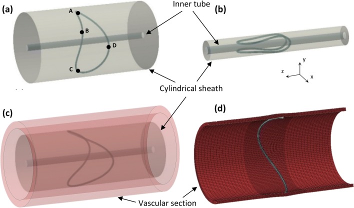
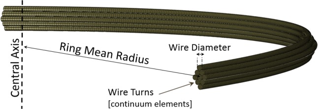
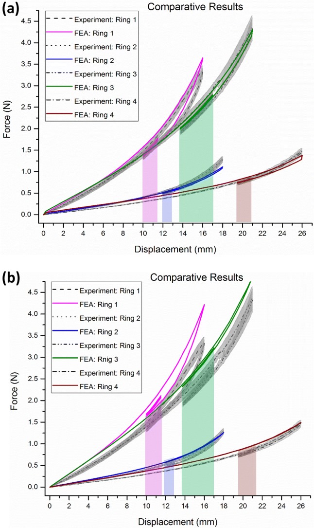
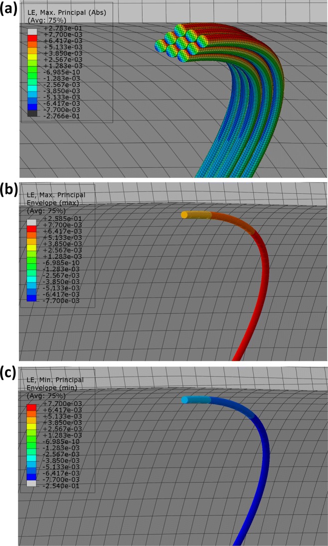
Ring stent bundles have been used in several biomedical stent-graft devices for decades, yet in the published literature, the numerical models of these structures always present significant simplifications. In this paper, a finite element (FE) ring stent bundle has been developed and evaluated with a combination of beam and surface elements. With this approach, the shape, the global stiffness and the strains of the structure can all be well predicted at a low computational cost while the approach is suitable for application to non-symmetrical, patient-specific implant simulations. The model has been validated against analytical and experimental data showing that the manufacturing strains can be predicted to a 0.1% accuracy and the structural stiffness with 0-7% precision. The model has also been compared with a more computationally expensive FE model of higher fidelity, revealing a discrepancy of 0-5% of the strain value. Finally, it has been shown that the exclusion of the manufacturing process from the simulation, a technique used in the literature, quadruples the analysis error. This is the first model that can capture the mechanical state of a full ring stent bundle, suitable for complex implant geometry simulations, with such accuracy.
Keywords: Anaconda; Aneurysm; Finite element analysis; Ring bundle; Stent.
Figures
References
-
- Auricchio F, Taylor RL, Lubliner J. Shape-memory alloys: macromodelling and numerical simulations of the superelastic behavior. Comput. Methods Appl. Mech. Eng. 1997;146:281–312. doi: 10.1016/S0045-7825(96)01232-7. - DOI
-
- Azaouzi M, Lebaal N, Makradi A, Belouettar S. Optimization based simulation of self-expanding Nitinol stent. Mater. Des. 2013;50:917–928. doi: 10.1016/j.matdes.2013.03.012. - DOI
-
- Boukis, A. A comprehensive methodology for the experimental characterization and numerical modelling of nickel-titanium wires used in medical devices. PhD dissertation, University of Strathclyde, 2019.
-
- Bow, D. Mechanical analysis and simulation of the nitinol ring stent: assessing the radial strength, fatigue and compaction strains. PhD dissertation, University of Strathclyde, 2018.
-
- Circles in a Circle. http://www.packomania.com/, 2018.
MeSH terms
Grants and funding
LinkOut - more resources
Full Text Sources
