. 2019 Aug;235(2):246-255.
doi: 10.1111/joa.13009. Epub 2019 May 9.

Visualisation of the vomerovaginal canal during endonasal transpterygoid approaches and CT imaging diagnosis

Affiliations

Visualisation of the vomerovaginal canal during endonasal transpterygoid approaches and CT imaging diagnosis

Qing-Guo Meng et al. J Anat. 2019 Aug.

Abstract

The vomerovaginal canal (VVC) and palatovaginal canal (PVC) are two canals that open forward to the posterior wall of the pterygopalatine fossa (PPF). Although the anatomy and computed tomography (CT) appearances of the PVC have been well studied, the VVC has been rarely reported, especially in endoscopic examinations. Some studies have even failed to distinguish the PVC from the VVC on CT images. The purpose of this study was to demonstrate the anatomy of the VVC on endoscopy and reveal its differences from the PVC, and to analyse the relative positions of the VVC, PVC, and pterygoid canal on CT images. Ten dry skull bases were studied to observe the structures involved in the formation of the VVC. Dissection of four cadaveric heads was performed to demonstrate the anatomy of the VVC on endoscopy. Coronal CT image analysis in 70 patients was conducted to evaluate the distances and relative positions between the VVC, PVC, and pterygoid canal. The PVC and VVC were also compared on axial CT images. The osteological study showed the top wall of the VVC was the antero-inferior wall of the sphenoid sinus. The VVC may be a helpful landmark in endoscopic endonasal transpterygoid approaches. Steps and discrimination in the dissections of the VVC and PVC were described. The interval between the PVC and VVC could be observed on both coronal and axial CT images. The coronal CT images of patients showed differences in the positions and distances among the three canals at both the anterior and posterior apertures of the PVC. The VVC can be easily mistaken for the PVC if its existence is not suspected. The anatomical morphologies and trajectories of the VVC and PVC differed on both nasal endoscopy and CT. The existence of the VVC should be considered during surgery and CT diagnosis within this area.

Keywords: endoscopy; palatovaginal canal; pterygopalatine fossa; transpterygoid approaches; vomerovaginal canal.


Conflict of interest statement

The authors declare that they have no conflict of interest.

Figures
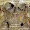
Figure 1
Figure 1
Relationships of the VVC, PVC, and pterygoid canal. Image and diagram of the roof of a dry skull base as observed from below. A, Anterior; L, Left; P, Posterior; R, Right.
Figure 2
Figure 2
Images from a dry skull base taken with a 0‐degree endoscope. (A) View of the roof of the nasopharynx seen from below. Note the VVC was medial to the PVC and connected to the pterygosphenoidal fissure, which was a suture that terminated at the pterygoid tubercle. (B‐D) Endoscopic view of the sphenopalatine foramen through the nose. (B) Note the copper probe exited from the anterior aperture of the right VVC and was located medial to the probe exiting from the PVC. (C) The middle part of the left sphenoid process was removed, and the silicon probe could be seen inside the PVC. (D) The left sphenoid process was completely removed. Note the VVC was deeper and longer than the PVC and posterior groove. It was formed by the vaginal process, the antero‐inferior wall of the sphenoid sinus, and the lateral edge of the vomer. A thin bony septum was observed between the PVC and VVC and gradually widened from the anterior to the posterior. (A) Green dashed line: orbital process of the palatine bone. Yellow dashed line: sphenopalatine foramen. Red dashed line: sphenoid process of the palatine bone. Blue dashed line: the second portion of the VVC. Purple dashed line: pterygosphenoidal fissure. Orange dashed line: pterygoid tubercle. A, Anterior; L, Left; P, Posterior; R, Right.
Figure 3
Figure 3
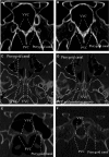
Coronal CT images of (A,B) skull specimens, and axial (C,D) and coronal (E,F) CT images of patients. (A) Coronal image at the level of the anterior aperture of the PVC. Note a tiny septum between the VVC and PVC. The VVC was superomedial to the PVC. The pterygoid canal was superior to the PVC and VVC. (B) Coronal image at the level of the posterior aperture of the PVC. The septum was relatively thick. Note the VVC ran superiorly to the inferior wall of the sphenoid sinus. The top wall of the PVC was not the antero‐inferior wall of the sphenoid sinus but the inferior surface of the vaginal process. The pterygoid canal was superior to the VVC, and the VVC was superior to the PVC. (C) Axial image at the level of the anterior aperture of the PVC. Note the medial canal was not the PVC but the VVC. Between the VVC and pterygoid canal appeared a short canal (here like a horn for its anterior aperture), which was the real PVC. (D) Axial image at the level of the posterior aperture of the PVC. Note that from lateral to medial, the right pterygoid canal, posterior groove, and VVC were simultaneously visualized. (E) Coronal image at the level of the anterior aperture of the PVC. The pterygoid canal, PVC, and VVC were almost on the same horizontal line. (F) Coronal image at the level of the posterior aperture of the PVC. The VVC was slightly higher than the PVC. The pterygoid canal was superior to the PVC and VVC.
Figure 4
Figure 4
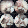
Endoscopic cadaveric dissection of the right nasal cavity of the No.1 fresh head with a 0‐degree endoscope. (A) Fibrous soft tissue was seen after the mucosa was separated from the posterior border of the sphenoid process and pushed backwards. (B) Part of the sphenoid process was removed. The posterior groove was identified, and the entire contents of the PVC could be displayed. (C) The contents of the VVC were clearly exposed after a piece of thin bone of the inner part of sphenoid process was removed completely. (D) Transection of the connection between the pharyngeal artery and the mucosa of the roof of nasopharynx. The contents of the PVC and VVC were removed, and the pterygopalatine ganglion was pushed outward. The posterior walls of the VVC and PVC (inferior surface of the vaginal process) were completely exposed after removal of the contents of these canals. A, Anterior; L, Left; P, Posterior; R, Right.
Figure 5
Figure 5
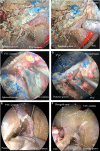
Endoscopic cadaveric dissection of the nasal cavity with a 0‐degree endoscope. (A,B) The left side of the No. 2 fresh head. (A) Part of the sphenoid process was removed. (B) The contents of the PVC and VVC were completely removed. Note the posterior part of the VVC here was a complete canal formed by the vaginal process and the lateral margin of vomer. (C,D) The left side of the No. 3 fresh head. (C) Note the pharyngeal artery and the contents of the VVC were clearly displayed after the sphenoid process of the palatine bone was removed. (D) The contents of the PVC and VVC were removed. Note the posterior wall of the PVC appeared as a shallow impression. (E,F) The right side of the No. 4 fresh head. (E) Note there was a septum between the PVC and VVC, and the probe raised the contents of the VVC. (F) The contents of the PVC had been removed. Note how the impression on the posterior groove was deeper than that by the PVC, and the VVC was obviously deeper than the PVC. A, Anterior; L, Left; P, Posterior; R, Right.
Figure 6
Figure 6
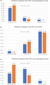
Relative positions of the VVC, PVC, and pterygoid canal on coronal CT images. Proximal = level of the anterior apertures of the PVC; distal = level of the posterior apertures of the PVC. (A) The relative positions of the PVC and pterygoid canal at the anterior and posterior apertures of the PVC. PC SUP = pterygoid canal superior to the PVC; PC INF = pterygoid canal inferior to the PVC. (B) The relative positions of the PVC and VVC at the anterior and posterior apertures of the PVC. PVC SUP = the PVC superior to the VVC; PVC INF = the PVC inferior to the VVC. (C) The relative positions of the VVC and pterygoid canal at the anterior and posterior apertures of the PVC. PC SUP = pterygoid canal superior to the VVC; PC INF = pterygoid canal inferior to the VVC.

References

    1. Borden NM, Dungan D, Dean BL, et al. (1996) Posttraumatic epistaxis from injury to the pterygovaginal artery. AJNR Am J Neuroradiol 17, 1148–1150. - PMC - PubMed
    1. Chen J, Xu F, Xiao J (2009) Anatomy of palatovaginal canal in normal adults: multi‐slice spiral CT and curved planar reconstruction studies. Chin J Radiol 43, 4.
    1. Chen CC, Chen ZX, Yang XD, et al. (2010) Comparative research of the thin transverse sectional anatomy and the multislice spiral CT on pterygopalatine fossa. Turk Neurosurg 20, 151–158. - PubMed
    1. Cheng Y, Gao H, Song G, et al. (2016) Anatomical study of pterygoid canal (PC) and palatovaginal canal (PVC) in endoscopic trans‐sphenoidal approach. Surg Radiol Anat 38, 541–549. - PubMed
    1. Chong VF, Fan YF (1997) Pterygopalatine fossa and maxillary nerve infiltration in nasopharyngeal carcinoma. Head Neck 19, 121–125. - PubMed

Publication types

LinkOut - more resources