. 2019:152:41-67.
doi: 10.1016/bs.mcb.2019.04.004. Epub 2019 Jun 8.

Serial-section electron microscopy using automated tape-collecting ultramicrotome (ATUM)

Affiliations

Serial-section electron microscopy using automated tape-collecting ultramicrotome (ATUM)

Valentina Baena et al. Methods Cell Biol. 2019.

Abstract

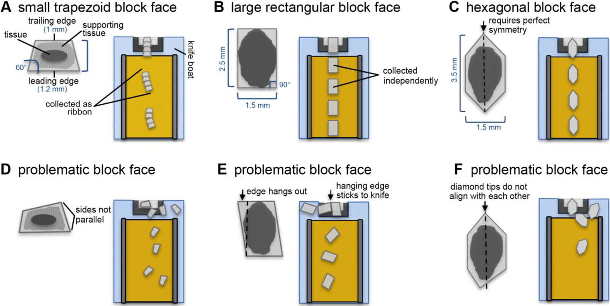
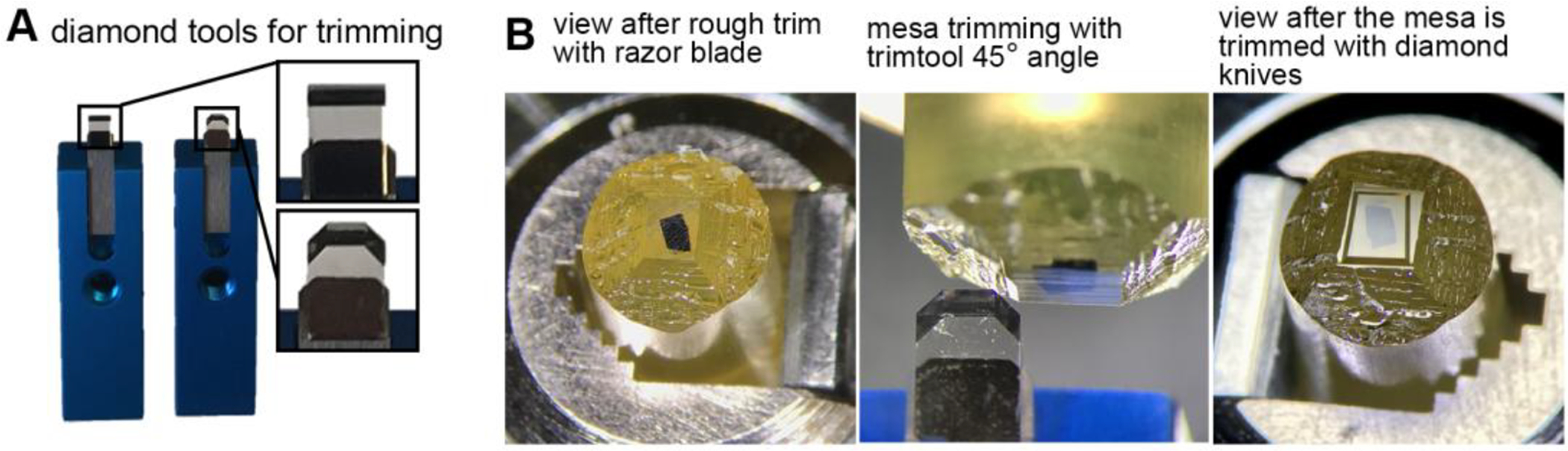
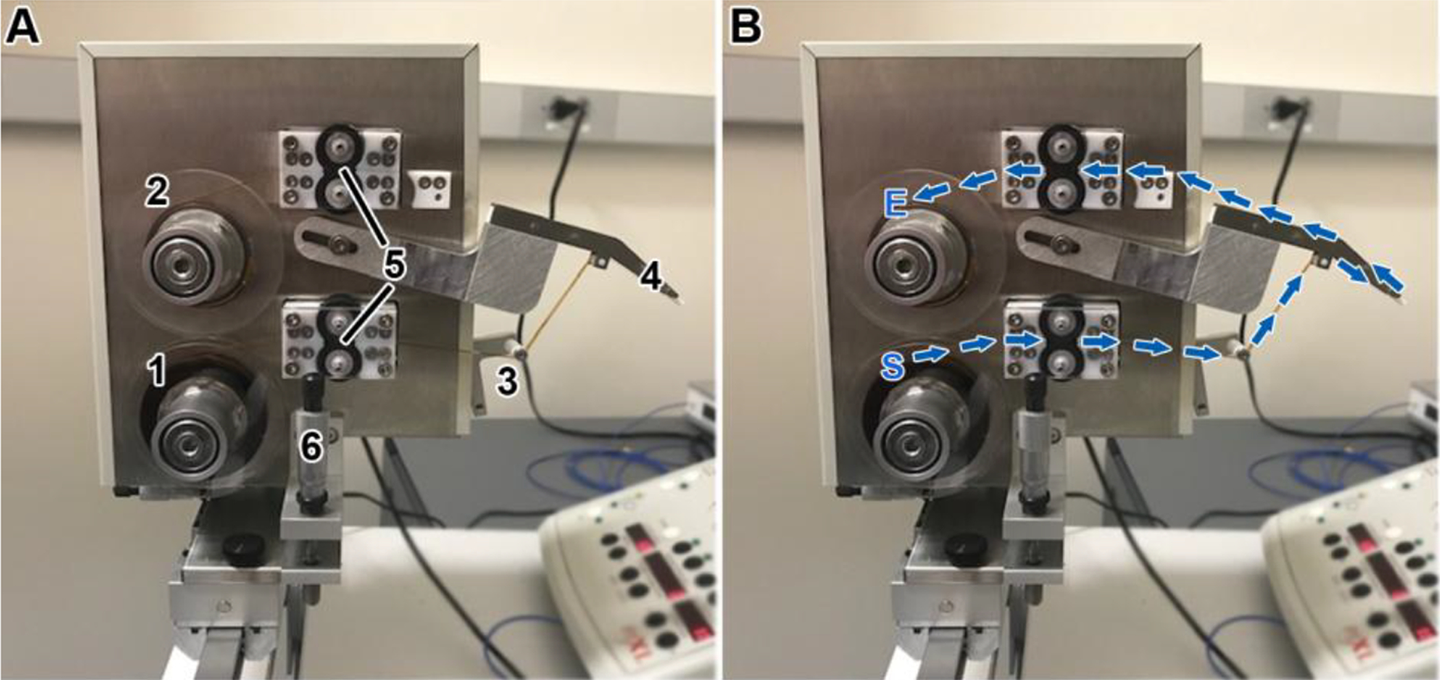
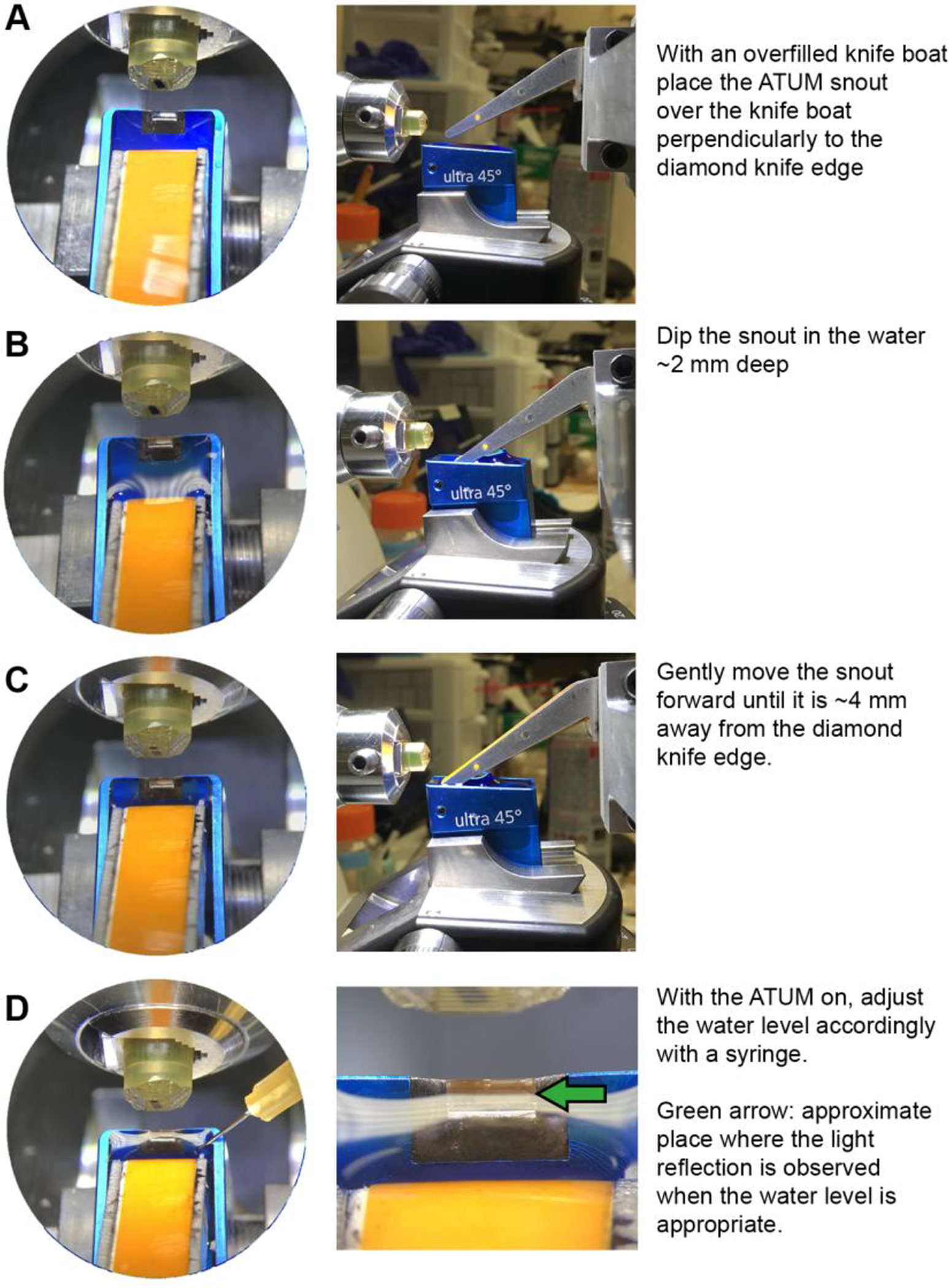
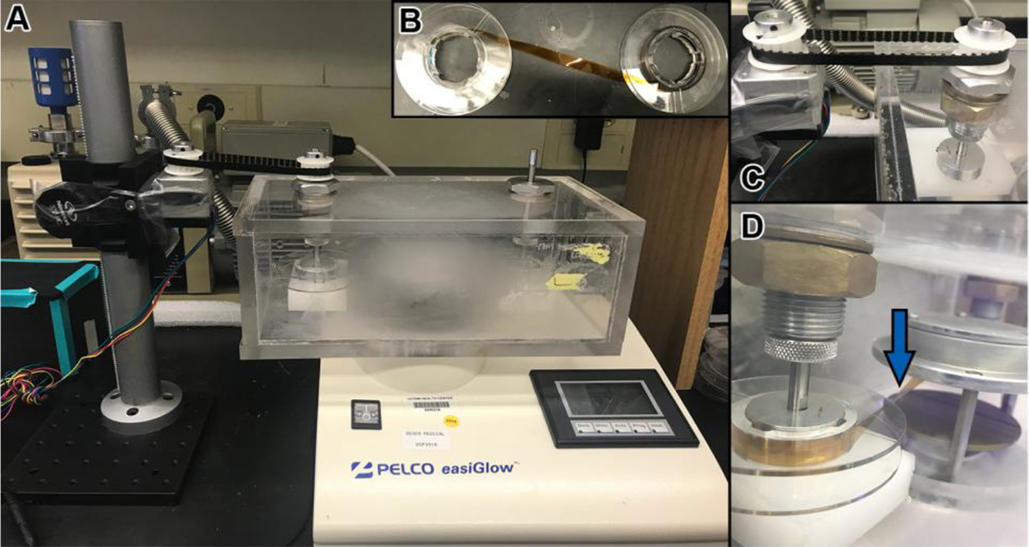
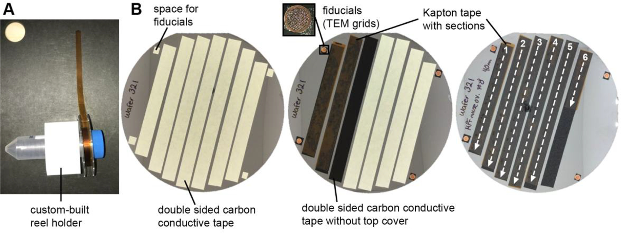
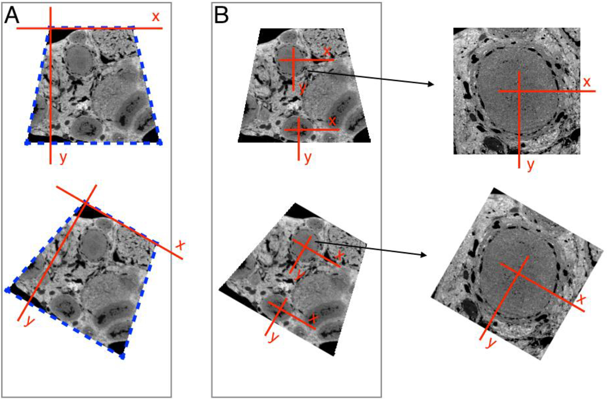
The Automated Tape-Collecting Ultramicrotome (ATUM) is a tape-reeling device that is placed in a water-filled diamond knife boat to collect serial sections as they are cut by a conventional ultramicrotome. The ATUM can collect thousands of sections of many different shapes and sizes, which are subsequently imaged by a scanning electron microscope. This method has been used for large-scale connectomics projects of mouse brain, and is well suited for other smaller-scale studies of tissues, cells, and organisms. Here, we describe basic procedures for preparing a block for ATUM sectioning, handling of the ATUM, tape preparation, post-treatment of sections, and considerations for mapping, imaging, and aligning the serial sections.

Keywords: 3D EM; ATUM; SEM; Serial section EM; Tape collector.


Figures

Figure 1.
Figure 1.. Schematic of typical block face shapes and a prediction on how they are picked up by the tape.
(A) A properly trimmed trapezoid block face tends to give sections that form ribbons. This shape is desirable when the block face is small. (B) A properly trimmed rectangular block face tends to give sections that are picked up independently. (C) An elongated hexagonal-shaped block face eliminates the formation of ribbons. (D) Example of an inappropriately trimmed block face. The leading and trailing edges are not parallel to each other. This leads to an abrupt rotation of the section after the trailing edge is cut, which may lead to some sections becoming stalled on the knife boat. (E) Example of an inappropriately trimmed block face. The trailing edge is longer on one side than the leading edge. The hanging edge tends to stick to the diamond knife edge, impeding the section from moving towards the tape. (F) Example of an inappropriately trimmed block face. The tips of the hexagonal-shaped block face do not align with each other, causing the sections to rotate in the knife boat.
Figure 2.
Figure 2.. Trimming a block for the ATUM.
(A) Common diamond trimming knives used for shaping the block face and mesa. A single edge-razor blade is used for an initial rough trimming, then, diamond trimming knives such as Trimtool 45° (left) and Trimtool 90° (right) (Diatome-US, Hatfield, PA) are used to shape and smoothen the block face and mesa. (B) Pictures of a block face during the trimming procedure. Left: A block face after rough trimming with a razor blade. Middle: trimming of the mesa with the side of a Trimtool 45° (Diatome-US, Hatfield, PA). Right: view of a trapezoid-shaped block face and mesa after trimming with diamond knives.
Figure 3.
Figure 3.. Components of the ATUM and path of the tape through the ATUM.
(A) Picture of the ATUM indicating its main components. (1) supply reel for the tape, (2) a take-up reel, (3) tape tensioner, (4) snout, (5) bottom and top pinch rollers, and (6) Z-height control. (B) The path of the tape begins at the supply reel (S), goes through the bottom pinch rollers (set in the “on” position), around the tensioner arm roller, around the snout, through the top pinch rollers, and ends at the take-up reel (E) to which it is attached with adhesive tape.
Figure 4.
Figure 4.. Procedure to position the ATUM snout in the knife boat.
(A-D) Panels on the left show view as seen from the ultramicrotome binoculars. Panels on the right show view as seen from the side (except for D, which shows view from binoculars). Text provides summarized procedure for placing the ATUM snout in the knife boat.
Figure 5.
Figure 5.. Glow discharge system for tape.
(A) Picture showing the PELCO easiGlow discharge unit (Ted Pella, Inc.) with a custom-made chamber. Within the chamber, the tape is passed from a source reel, through the glow discharge area, and is then collected on a take-up reel. The take-up reel is turned by a motor and a belt system (left). (B) Before placing the tape in the chamber, it is attached from the source reel to the take-up reel with adhesive tape. (C) Motor and belt system for turning reels with tape. (D) One of the reels is turned accordingly so that the tape runs parallel to the discharge plates and the underside of the tape (the side which will collect the sections) faces up as it runs in between the plates (blue arrow).
Figure 6.
Figure 6.. Mounting tape with sections on a wafer.
(A) A custom-built reel holder holing a reel with tape with sections. The tape has been spread over a cutting board so that it can be cut into strips. (B) Procedure showing how a wafer is made. Left: strips of double sided carbon conductive tape are laid down along the wafer surface. Small squares for adhering fiducials are placed where appropriate. Middle: the Kapton tape with sections is cut into strips that are then placed over the adhesive carbon tape guides. Right: The orientation and order of the strips of tape should be kept consistent throughout the wafer. In this case, the order of the sections goes from top to bottom and from left to right. The wafer will be mapped in this order.
Figure 7.
Figure 7.. Two different strategies for mapping sections.
(A) With the Atlas 5 AT software, a template for the section outline is made of the first section (blue dashed lines), and this is aligned with each of the following sections. The origin of the coordinate system for each section is at one corner of the section. (B) In the alternative method, the coordinate system is defined relative to a biological structure in the specimen. An alignment algorithm operates on the image, and shifts the origin from section to section. The text explains in detail why this is advantageous. Briefly, this procedure locates the coordinate system origin with higher accuracy. In addition, a local coordinate system reduces mapping errors due to wrinkles / compression in the sections.

References

    1. Ai-Awami AK, Beyer J, Haehn D, Kasthuri N, Lichtman JW, Pfister H, & Hadwiger M (2016). NeuroBlocks--Visual Tracking of Segmentation and Proofreading for Large Connectomics Projects. IEEE Transactions on Visualization and Computer Graphics, 22(1), 738–746. 10.1109/TVCG.2015.2467441 - DOI - PubMed
    1. Baena V, & Terasaki M (2019). Three-dimensional organization of transzonal projections and other cytoplasmic extensions in the mouse ovarian follicle. Scientific Reports, 9(1), 1262. 10.1038/s41598-018-37766-2 - DOI - PMC - PubMed
    1. Berger DR, Seung HS, & Lichtman JW (2018). VAST (Volume Annotation and Segmentation Tool): Efficient Manual and Semi-Automatic Labeling of Large 3D Image Stacks. Frontiers in Neural Circuits, 12. 10.3389/fncir.2018.00088 - DOI - PMC - PubMed
    1. Bozzola JJ, & Russell LD (1999). Electron Microscopy: Principles and Techniques for Biologists. Jones & Bartlett Learning.
    1. Eberle AL, Mikula S, Schalek R, Lichtman J, Tate MLK, & Zeidler D (2015). High-resolution, high-throughput imaging with a multibeam scanning electron microscope. Journal of Microscopy, 259(2), 114–120. 10.1111/jmi.12224 - DOI - PMC - PubMed

LinkOut - more resources