Review
. 2019 Apr 18;6(12):1802373.
doi: 10.1002/advs.201802373. eCollection 2019 Jun 19.

Structural Engineering of Low-Dimensional Metal-Organic Frameworks: Synthesis, Properties, and Applications

Affiliations
Review

Structural Engineering of Low-Dimensional Metal-Organic Frameworks: Synthesis, Properties, and Applications

Wenxian Liu et al. Adv Sci (Weinh). .

Abstract

Low-dimensional metal-organic frameworks (LD MOFs) have attracted increasing attention in recent years, which successfully combine the unique properties of MOFs, e.g., large surface area, tailorable structure, and uniform cavity, with the distinctive physical and chemical properties of LD nanomaterials, e.g., high aspect ratio, abundant accessible active sites, and flexibility. Significant progress has been made in the morphological and structural regulation of LD MOFs in recent years. It is still of great significance to further explore the synthetic principles and dimensional-dependent properties of LD MOFs. In this review, recent progress in the synthesis of LD MOF-based materials and their applications are summarized, with an emphasis on the distinctive advantages of LD MOFs over their bulk counterparties. First, the unique physical and chemical properties of LD MOF-based materials are briefly introduced. Synthetic strategies of various LD MOFs, including 1D MOFs, 2D MOFs, and LD MOF-based composites, as well as their derivatives, are then summarized. Furthermore, the potential applications of LD MOF-based materials in catalysis, energy storage, gas adsorption and separation, and sensing are introduced. Finally, challenges and opportunities of this fascinating research field are proposed.

Keywords: catalysts; electrode materials; low‐dimensional nanomaterials; metal–organic frameworks; sensors.


Conflict of interest statement

The authors declare no conflict of interest.

Figures

Figure 1
Figure 1
Unique properties of low‐dimensional (LD) MOF‐based materials and their applications. Top left: some representative examples of LD MOF‐based materials used as catalysts. Hydrosilylation of olefins. Reproduced with permission.64 Copyright 2016, Wiley‐VCH. OER & ORR. Reproduced with permission.65 Copyright 2018, Wiley‐VCH. CO2 photoreduction. Reproduced with permission.66 Copyright 2015, Royal Society of Chemistry. Top right: some representative examples of LD MOF‐based materials used in the field of gas adsorption and separation. H2/CO2 separation. Reproduced with permission.67 Copyright 2017, Wiley‐VCH. Air filter. Reproduced with permission.70 Copyright 2016, American Chemical Society. Gas adsorption. Reproduced with permission.68 Copyright 2017, American Chemical Society. Bottom left: some representative examples of LD MOF‐based materials used in the field of energy storage. Flexible supercapacitors. Reproduced with permission.73 Copyright 2015, Wiley‐VCH. Zn‐air batteries. Reproduced with permission.71 Copyright 2018, Wiley‐VCH. Lithium‐ion batteries. Reproduced with permission.72 Copyright 2016, Wiley‐VCH. Bottom right: some representative examples of LD MOF‐based materials used as sensor. Detection of H2O2. Reproduced with permission.74 Copyright 2013, American Chemical Society. Detection of DNA. Reproduced with permission.75 Copyright 2015, Wiley‐VCH. Detection of uric acid. Reproduced with permission.69 Copyright 2017, Royal Society of Chemistry. Middle: some representative examples of LD MOF‐based materials. Bottom left image in 1D MOFs panel. Reproduced with permission.91 Copyright 2017, Elsevier. Top right image in 1D MOFs panel. Reproduced with permission.97 Copyright 2009, Wiley‐VCH. Top left image in 2D MOFs panel. Reproduced with permission.168 Copyright 2016, Wiley‐VCH. Bottom right image in 2D MOFs panel. Reproduced with permission.82 Copyright 2014, Springer Nature. Left image in composites and derivatives panel. Reproduced with permission.112 Copyright 2014, American Chemical Society. Right image in composites and derivatives panel. Reproduced with permission.214 Copyright 2016, Wiley‐VCH.
Figure 2
Figure 2
The summary of publications regarding to LD MOF‐based materials in recent years (2010–2018), as searched by “Web of Science” (until 2018 December 20).
Figure 3
Figure 3
Schematic illustration of two typical preparation strategies for 1D MOFs.
Figure 4
Figure 4
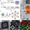
TEM images of a) ZIF8‐100‐N nanorods, b) ZIF8‐100‐A nanotubes, and c) ZIF8‐30‐N nanowires. Reproduced with permission.54 Copyright 2018, Wiley‐VCH. d) Schematic illustration of the preparation procedure for Cd‐BTC MOF nanotubes. e–h) TEM images of the obtained samples in different reaction stages. Reproduced with permission.105 Copyright 2011, Wiley‐VCH.
Figure 5
Figure 5
a) Schematic illustration of the preparation of Mn‐ICG@pHis‐PEG nanofibers. b) TEM images of Mn‐ICG@pHis‐PEG obtained in different solutions. c) STEM‐mappings of Mn‐ICG@pHis‐PEG nanofibers. Reproduced with permission.52 Copyright 2017, Wiley‐VCH. d) Scheme of the modulator‐assisted synthetic process of MOF‐74 rods. Reproduced with permission.140 Copyright 2016, Springer Nature. e) Crystal structure of a Cu‐CAT showing 1D channels along the c‐axis with open‐window size of 1.8 nm. SEM images of f) carbon fiber paper, and g,h) the Cu‐CAT nanowire arrays grown on a carbon fiber paper. Reproduced with permission.89 Copyright 2017, Wiley‐VCH.
Figure 6
Figure 6
Timeline of important breakthroughs in the synthesis of 2D MOF nanosheets. Reproduced with permission.147 Copyright 2010, Royal Society of Chemistry. Reproduced with permission.148 Copyright 2010, Springer Nature. Reproduced with permission.149 Copyright 2012, American Chemical Society. Reproduced with permission.150 Copyright 2014, Wiley‐VCH. Reproduced with permission.82 Copyright 2015, Springer Nature. Reproduced with permission.151 Copyright 2016, Springer Nature. Reproduced with permission.152 Copyright 2017, Royal Society of Chemistry. Reproduced with permission.153 Copyright 2018, Royal Society of Chemistry.
Figure 7
Figure 7
Schematic illustration of the three typical preparation strategies for 2D MOFs.
Figure 8
Figure 8
a) Crystal structure of Zn‐C12H14O4 MOF showing no chemical bond between its layers. Reproduced with permission.158 Copyright 2008, Royal Society of Chemistry. b) AFM image of the exfoliated Mn‐DMS nanosheet, and c) the corresponding height profiles. Reproduced with permission.159 Copyright 2011, American Chemical Society. d) Crystal structure of layered Zn2(bim)4 showing each Zn ion is coordinated by 4 benzimidazole ligands in a distorted tetrahedral geometry. e) SEM images of the bulk Zn2(bim)4 precursor. f) TEM image of Zn2(bim)4 nanosheets. Reproduced with permission.160 Copyright 2014, American Association for the Advancement of Science.
Figure 9
Figure 9
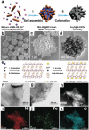
a) Schematic illustration of the traditional and surfactant‐assisted synthetic processes for TCPP‐based MOFs. b) TEM and AFM images of ultrathin Zn‐TCPP nanosheets. Reproduced with permission.75 Copyright 2015, Wiley‐VCH. c) Schematic illustrations of the Hf6 secondary building unit (SBU) (left), and the BTB ligand (right). d) Crystal structure and e) TEM image of Hf6O4(OH)4‐(HCO2)6(BTB)2 nanosheets. Reproduced with permission.64 Copyright 2016, Wiley‐VCH. f) TEM image, g) HAADF‐STEM image, and h) EDX elemental mappings of hierarchical Zn/Ni‐MOF‐2 nanosheet‐assembled hollow nanocubes. Reproduced with permission. Copyright 2014, Wiley‐VCH.150
Figure 10
Figure 10
a) Schematic illustration of the fabrication procedure for TCPP(Co)‐pyridine‐Cu MOF nanofilms. Reproduced with permission.148 Copyright 2010, Springer Nature. b) Schematic illustration of the interfacial synthesis of bis(dipyrrinato)zinc(II) complex nanosheets at the interface of H2O and CH2Cl2. Reproduced with permission.188 Copyright 2015, Springer Nature. c) Schematic illustration of the fabrication process for Fe(pyridine)2[Pt(CN)4] thin film at liquid/solid interface. Reproduced with permission.193 Copyright 2016, Springer Nature.
Figure 11
Figure 11
a) Schematic illustration of the synthetic process for MIL‐88@ZIF‐8 composite and its derivative. b,c) FESEM and d) TEM images of MIL‐88@ZIF‐8 composites. Reproduced with permission.215 Copyright 2016, Royal Society of Chemistry. e) Schematic illustration of the preparation process for Ni‐MOF/Fe‐MOF composite nanosheet. TEM images of f) Ni‐MOF and g) Ni‐MOF/Fe‐MOF composite nanosheet. h–k) HAADF‐STEM image and corresponding elemental mappings of Ni‐MOF@Fe‐MOF hybrid nanosheets. Reproduced with permission.216 Copyright 2018, Wiley‐VCH.
Figure 12
Figure 12
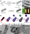
a) Schematic illustration of synthetic process for hierarchical Cu‐based MOF nanoarrays. b,c) SEM and d) TEM images of hierarchical MOF‐2 nanoarrays. SEM images of e) Cu‐based MOF nanoarrays with different ligands of Br‐H2BDC, and f) 1,4‐H2NDC. Reproduced with permission.226 Copyright 2017, Wiley‐VCH. TEM images of g) ZnO nanorods@Au, and h,i) ZnO nanorods@Au@ZIF‐8 composites with Au NPs at different locations. Reproduced with permission.116 Copyright 2017, Springer Nature. j) Schematic illustration showing the preparation process for the CuS/Cu‐TCPP composite nanosheet. k) TEM and l) HRTEM image of the CuS/Cu‐TCPP composite nanosheets. m) Dark‐field STEM image of CuS/Cu‐TCPP composite nanosheets and the corresponding elemental mapping. Reproduced with permission.214 Copyright 2016, Wiley‐VCH. n) Schematic illustration of the synthetic process and o) SEM image of hierarchical NH2‐MIL‐68@TPA‐COF composite. Reproduced with permission.211 Copyright 2017, Wiley‐VCH.
Figure 13
Figure 13
a) Schematic illustration of synthetic process for the rod‐like rGO/MoO3 composite. b) TEM image and c) Raman mappings of the rGO/MoO3 composite. Reproduced with permission.73 Copyright 2015, Wiley‐VCH. d) Schematic illustration of the preparation of hierarchical CNT/Co3O4 microtubes. e–g) TEM images of the hierarchical CNT/Co3O4 microtubes. Reproduced with permission.244 Copyright 2016, Wiley‐VCH.
Figure 14
Figure 14
a) Schematic illustration of the preparation of 2D porous Co3O4/ZnO hybrid nanosheets. b–e) Elemental mappings of the Co3O4/ZnO nanosheets. Reproduced with permission.248 Copyright 2017, Royal Society of Chemistry. f) Schematic illustration of the formation process for 2D CoS1.097 NPs/nitrogen‐doped carbon (CoSNC) nanosheets. g) AFM, h) TEM, and i) HRTEM images of 2D CoSNC nanosheets. Reproduced with permission.169 Copyright 2016, American Chemical Society.
Figure 15
Figure 15
a) TEM image of ultrathin Ni/Co MOF nanosheets. The inset shows the Tyndall light scattering of composite solution. b) HAADF‐STEM image of the (200) plane of ultrathin Ni/Co MOF nanosheets, which shows hexagonal crystal lattice for the metal atoms (pink color). Among them, the green color stands for background and the blue represents carbon and oxygen. c) Schematic illustration of the electronic coupling between Co and Ni in NiCo‐UMOFNs. Reproduced with permission.151 Copyright 2016, Springer Nature. d) SEM image, and e) AFM image with corresponding height profile of NiFe‐MOF nanosheets. f) LSV plots of the electrocatalytic water splitting cell based on NiFe‐MOF electrodes, and the cell using a Pt/C cathode and a IrO2 anode. Reproduced with permission.278 Copyright 2017, Springer Nature.
Figure 16
Figure 16
a) Schematic illustration of the modification of the SBUs of 2D FeII/Hf‐TPY nanosheet by using gluconic acid, which regulated the hydrophobicity/hydrophilicity around the active sites of MOFs. Microscopy images of b) water droplets on different FeII/Hf‐TPY films of as‐synthesized film, c) oleic acid‐modified film, and d) gluconic acid‐modified film. e) Relationship between butyrolactone selectivity and contact angles of FeII/Hf‐TPY nanosheet in the aerobic oxidation of tetrahydrofuran. Reproduced with permission.300 Copyright 2017, Wiley‐VCH. f) Scheme of the Knoevenagel condensation of benzaldehyde with malononitrile to produce benzylidenemalononitrile, which was catalyzed by the AAO/MIL‐53‐NH2 composite membrane. Reproduced with permission.304 Copyright 2016, Wiley‐VCH.
Figure 17
Figure 17
a) SEM, b) TEM, and c) HRTEM images of MnO@Co–N/C composite nanowires. d) Schematic illustration of a fabricated Zn–air battery. e) Discharge polarization curves and corresponding power densities of the Zn–air battery. Reproduced with permission.243 Copyright 2018, Royal Society of Chemistry.
Figure 18
Figure 18
a) AFM image and b) crystal structure of Zn2(Bim)3 nanosheets, where the green symbol presents Zn, the orange one stands for N, and the gray one is for C. c) Cross‐sectional SEM image and d) single gas permeation of a Zn2(bim)3 nanosheet membrane obtained at 200 °C. e) Binary gas separation performance of equimolar H2/CO2 of the obtained Zn2(bim)3 nanosheet membranes at different temperatures. Reproduced with permission.67 Copyright 2017, Wiley‐VCH.
Figure 19
Figure 19
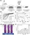
a) Schematic illustration of the preparation process for the 2D MOF nanosheet‐based thin films. b) Cyclic voltammetry curves at a scan rate of 50 mV s−1 and c) typical amperometric response at an applied potential of −50 mV of bare GC electrode and various GC/(Co‐TCPP(Fe))n (n = 1–6) electrodes in 0.1 m PBS (pH 7.4) with 0.5 × 10⁻³ m H2O2. Reproduced with permission.168 Copyright 2017, Wiley‐VCH. d) Schematic illustration of the ZnO@ZIF‐CoZn core‐sheath nanowire array. e) Gas sensing properties of ZnO@ZIF‐CoZn toward acetone vapor. Reproduced with permission. Reproduced with permission.115 Copyright 2016, Wiley‐VCH.

Similar articles

Cited by

References

    1. Furukawa H., Cordova K. E., O'Keeffe M., Yaghi O. M., Science 2013, 341, 1230444. - PubMed
    1. Schneemann A., Bon V., Schwedler I., Senkovska I., Kaskel S., Fischer R. A., Chem. Soc. Rev. 2014, 43, 6062. - PubMed
    1. Wang W., Xu X., Zhou W., Shao Z., Adv. Sci. 2017, 4, 1600371. - PMC - PubMed
    1. Zhao W., Peng J., Wang W., Liu S., Zhao Q., Huang W., Coord. Chem. Rev. 2018, 377, 44.
    1. Ding X. J., Jiang H. L., Acc. Chem. Res. 2019, 52, 356. - PubMed

LinkOut - more resources