Review
. 2019 Dec;48(8):20190205.
doi: 10.1259/dmfr.20190205. Epub 2019 Aug 13.

The maxillary sinus: physiology, development and imaging anatomy

Affiliations
Review

The maxillary sinus: physiology, development and imaging anatomy

Andrew Whyte et al. Dentomaxillofac Radiol. 2019 Dec.

Erratum in

Abstract

Objectives: The maxillary sinus is of paramount importance for otolaryngologists, rhinologists, oral and maxillofacial surgeons, head and neck and dental and maxillofacial radiologists. A comprehensive review article concerning the physiology, development and imaging anatomy was undertaken.

Methods: Relevant literature pertaining to the physiology of the sinonasal cavity, development of the paranasal sinuses and imaging anatomy of the maxilla and maxillary sinus from 2000 to 2019 was reviewed. Emphasis was placed on literature from the last 5 years.

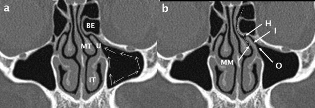
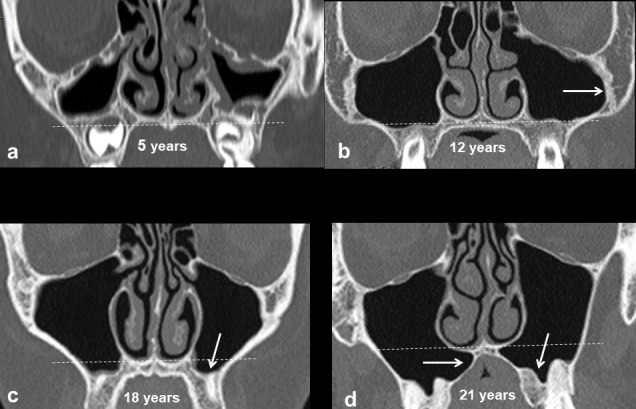
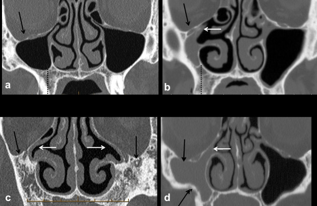
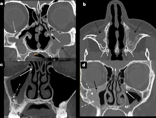
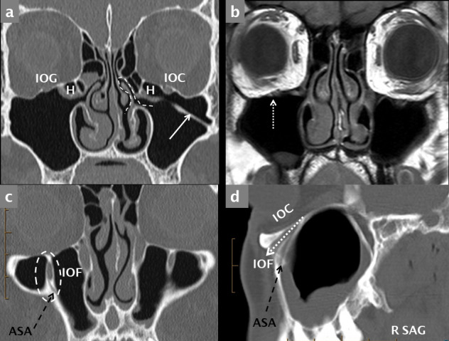
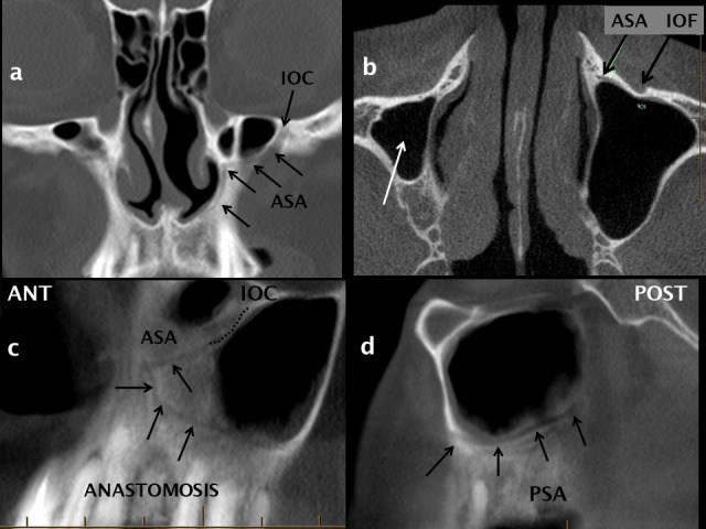
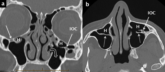
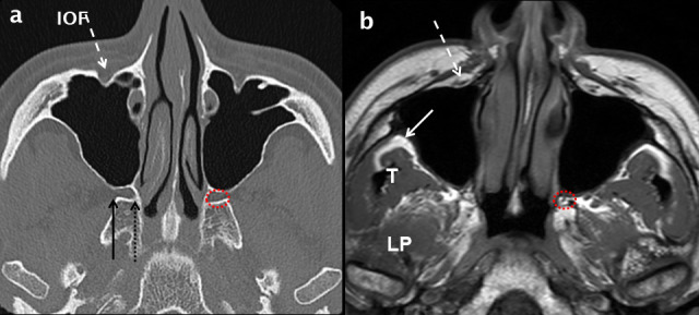
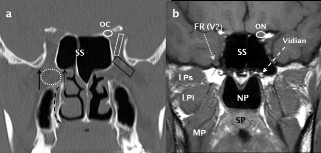
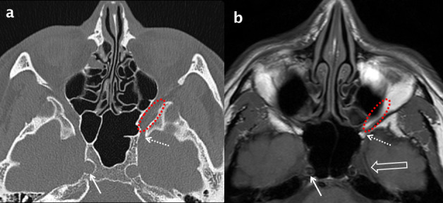
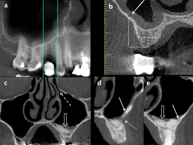
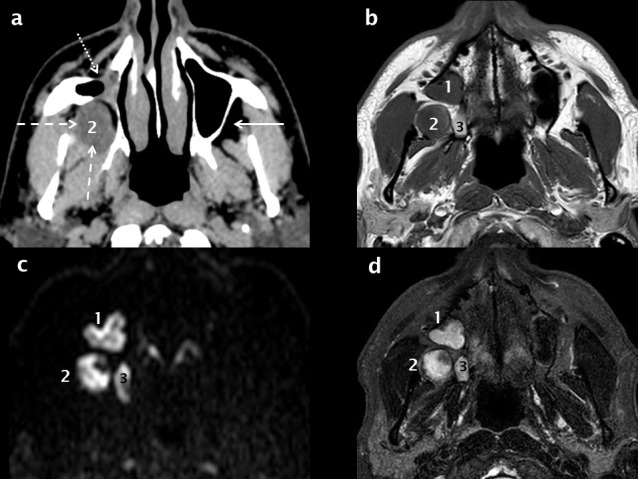
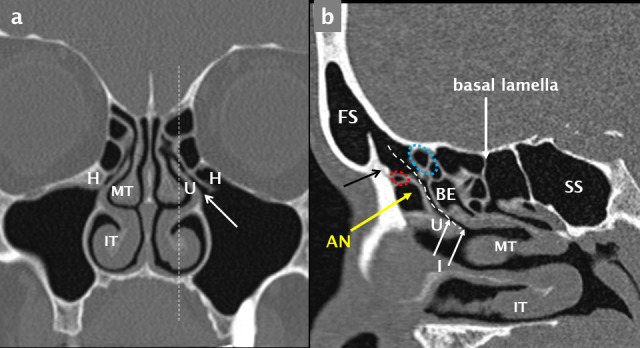
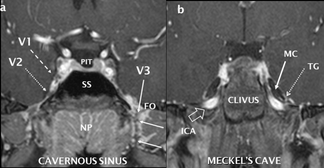
Results: Extensive recent research using imaging has provided new insights into the development of the maxillary sinus, the other paranasal sinuses and the midface. The fundamental physiological concept of mucociliary clearance and its role in sinus health is emphasized. The paranasal sinuses are an integral part of a common mucosal organ formed by the upper and lower airway.An in-depth understanding of the soft-tissue and neurovascular relationships of the maxillary sinus to the deep fascial spaces and branches of the trigeminal nerve and external carotid artery respectively is required to evaluate and report imaging involving the maxillary sinus.Sinusitis of rhinogenic, rather than odontogenic origin, originates from nasal inflammation followed by anterior ethmoid disease and secondary obstruction of the ostiomeatal unit. The role of anatomical variants that predispose to this pattern of disease is discussed in detail with illustrative examples.The maxillary sinus is intimately related to the roots of the posterior maxillary teeth; the high frequency of mucosal disease and sinusitis of odontogenic aetiology is now well recognized. In addition, an understanding of the anatomy of the alveolar process, morphology of the alveolar recess of the maxillary sinus and neurovascular supply are essential both for deliberate surgical intervention of the sinus and complications related to oral surgical procedures.

Conclusions: An understanding of the fundamental principles of the development, physiology, anatomy and relationships of the maxillary sinus as depicted by multi-modality imaging is essential for radiologists reporting imaging involving the paranasal sinuses and midface.

Keywords: Dentition – Anatomy; Diagnostic Imaging; Maxillary Sinus; Physiology.


Figures

Figure 1.
Figure 1.
The ostiomeatal unit/ complex. Cilia propel mucus (white arrows in a) towards the sinus ostium (O); it then passes via the infundibulum (I) to the hiatus semilunaris (H) and into the middle meatus (MM). The path of drainage of mucus from the frontal sinus via the frontal recess is shown by the white dashed line in b. The anatomical boundaries of the OMU/ C include the uncinate process (U), middle turbinate (MT), inferior turbinate (IT) and the most prominent anterior ethmoid air cell: bulla ethmoidalis (BE).
Figure 2.
Figure 2.
Development of the maxillary sinuses. Up to the age of 12 years, growth of the maxillary sinus is predominantly in a lateral direction towards the zygoma creating the zygomatic recess (white arrow in b) and inferiorly to the level of the hard palate. Thereafter, the sinus expands inferiorly below the level of the nasal floor (white arrows in c, d).
Figure 3.
Figure 3.
Hypoplasia and aplasia versus chronic atelectasis of the maxillary sinuses. Mild hypoplasia of the right maxillary sinus (a) is associated with a normal uncinate process and patent ostiomeatal unit; there is mild depression of the right orbital floor (black arrow). The uncinate process is hypoplastic and lateralized occluding the right infundibulum in a case of marked hypoplasia (b); the right maxillary sinus is opaque and there is asymmetric increase in height of the right alveolar process. Aplasia of the maxillary sinuses (c) associated with a lateralized and hypoplastic right uncinate process and absence of the left uncinate process (white arrows). In chronic maxillary sinus atelectasis (d), the orbital floor is inferiorly situated (black arrows) increasing orbital volume. There is contraction of the right maxillary sinus with depression of the orbital floor and retraction of the inferolateral wall (black arrows). The right infundibulum is narrow and occluded (white arrow); the absence of increase in height of the alveolar process (compare with dotted black line in a–b) confirms this as chronic maxillary sinus atelectasis (silent sinus syndrome) rather than hypoplasia.
Figure 4.
Figure 4.
Other causes of a small maxillary sinus. Caldwell–Luc procedures (black arrows) result in thick-walled and contracted maxillary sinuses which are commonly opaque (a, b). There is depression of the orbital floor (dotted white arrow in a) and the left ostiomeatal unit is occluded (solid white arrow in a) and narrowed by an adjacent Haller cell (H). Chronic odontogenic sinusitis (c) secondary to periapical sepsis associated with 16 (dot-dash white arrow); there is peripheral mucosal thickening in a mildly contracted and thick-walled right maxillary sinus with occlusion of the ostium (white arrow). In d, peripheral bone formation with aground-glass texture typical of fibrous dysplasia (dashed white arrows) constricts the lumen of the right maxillary sinus and surrounds the infraorbital canal (black arrow). There is moderate mucosal thickening in the left maxillary sinus (MT) with occlusion of the left ostium and infundibulum (white arrow) which is narrowed by a Haller cell (H).
Figure 5.
Figure 5.
Normal coronal anatomy. Bone-window MDCT coronal reconstruction (a) and T1 weighted coronal MRI scan (b) through the maxillary sinuses demonstrating an IOG on the right and an IOC on the left. The right infraorbital nerve and vessels are indicated (dotted white arrow) on the MRI image (b). Coronal (c) sagittal (d) reconstructions through the anterior maxilla demonstrate the IOF (dashed white oval in c) and the canaliculus sinuosus (ASA neurovascular canal, dashed black arrows). ASA: anterior superior alveolar canal; IOC: infraorbital canal; IOF: infraorbital foramen; IOG: infraorbital groove.
Figure 7.
Figure 7.
The anterior superior alveolar neurovascular canal and anastomotic arcade. The ASA neurovascular canal (canaliculus sinuosus) originates from the IOC as shown on coronal (a), axial (b) and oblique (c) reconstructions from a CBCT scan. The ASA canal courses inferiorly and medially (black arrows in a + c) following a sinuous course adjacent to the pyriform aperture of the nose towards the anterior maxillary teeth. The ASA and PSA neurovascular canals anastomose (c, d) to form an arcade which supplies the anterolateral sinus wall, the mucosa and the maxillary teeth. ASA:anterior superior alveolar canal; CBCT: cone beam CT; IOC: infraorbital canal; PSA: posterior superior alveolar canal
Figure 6.
Figure 6.
Haller cells, septa and prolapse of the infraorbital canal into the maxillary sinus. Haller cells (H) are shown on coronal (a) and axial (b) bone window reconstructions from a multidetector CT scan. These ectopic air cells narrow the diseased infundibulum bilaterally. The axial image (b) optimally demonstrates the associated septa (white dotted arrows) and the prolapse of the left infraorbital neurovascular canal (IOC) into the anterosuperior aspect of the left maxillary sinus. There has been a previous left inferior meatal antrostomy (right-angle white open arrow in a).
Figure 8.
Figure 8.
Normal axial anatomy at the mid maxillary sinus level. Comparative axial MDCT (a) and T1 weighted MRI (b) images through the mid maxillary sinus level demonstrating bone and soft-tissue anatomy. The infra orbital neurovascular complex (white dashed arrows) is shown within the IOF. Peripheral to the lateral wall of the maxillary sinus, the infratemporal fossa (white arrow in b) is an important deep fascial space. The muscles of the medial aspect of the masticator space: temporalis (T) and LP are shown (b). The PPF (dotted red circle in a and b) contains fat, vessels and nerves. Its lateral boundary is the pterygomaxillary fissure (solid black arrow in a) which communicates with the infratemporal fossa. At the superomedial margin of the PPF is the sphenopalatine foramen (dotted black arrow in a) which is in continuity with the nasal cavity. IOF:infraorbital foramen; LP: lateral pterygoid; MDCT: multidetector CT; PPF: pterygopalatine fossa.
Figure 10.
Figure 10.
Normal coronal anatomy through the pterygopalatine fossa. A coronal bone-window MDCT image (a) shows the PPF (dotted white oval) and its lateral (pterygomaxillary fissure: black arrow) and medial (sphenopalatine foramen: short dotted black arrow) boundaries. The inferior orbital fissure (black trapezoid) and superior orbital fissure (white trapezoid) are also indicated. The descending palatine canal is indicated by a curved, dashed black line. Directly posterior to the PPF, a T1 weighted MRI image (b) demonstrates the FR (dotted white arrow) containing the V2 nerve and also the Vidian canal (dashed white arrow). The ON (b) is shown in the OC (a) and the NP, SP, MP and the superior and inferior heads of LP (LPs and LPi respectively) are indicated (b). LP: lateral pterygoid; MP: medialpterygoid; NP: nasopharynx; OC: optic canal; ON: optic nerve; SP:soft palate.
Figure 9.
Figure 9.
Normal axial anatomy at the superior margin of the maxillary sinus. Comparative bone window MDCT (a) and T1 weighted MRI (b) axial images through the superior aspect of the maxillary sinuses. Inferiorly, the inferior orbital fissure (dotted red oval) is contiguous with the PPF and posteriorly with the foramen rotundum (dotted white arrows). Meckel’s cave (open white arrow in b) and the internal carotid artery (white arrows) are also demonstrated. PPF: pterygopalatine fossa; MDCT: multidetector CT.
Figure 11.
Figure 11.
Assessment for implant placement in the posterior maxilla using CBCT. A panoramic reconstruction of the right posterior maxillary quadrant (a) shows a stent marker indicating the proposed site for implant placement in the 15 region and the location of radial reconstructions. The height and width (dashed white lines) of alveolar bone can be measured on a radial reconstruction through the mid-point of the edentulous segment (b). The position of the PSA canal is indicated by a white arrow; it is in a submucosal position and just less than 1 mm in diameter. The height of the PSA from the alveolar crest can be measured (dotted white lines). A sinus lift procedure and guided bone regeneration in the left posterior maxilla are shown on coronal (c) and radial (d, e) reconstructions from a CBCT scan. Mild mucosal thickening overlies the consolidated bone graft (open white arrow in a) and the left OMU (dashed white arrow) is patent. The surgical cut for the bone window (dotted white arrow in d) and a tiny intraosseous PSA (solid white arrow in d and e) are shown. CBCT: cone beam CT; OMU: ostiomeatal unit; PSA: posterior superior alveolar.
Figure 12.
Figure 12.
MRI and the detection of recurrent OKC. The right maxillary sinus is contracted (white dotted arrow) secondary to a previous CaldwellLuc procedure for excision of a right posterior maxillary OKC as seen on an axial soft-tissue window MDCT reconstruction (a). There is recurrent OKC in the right infratemporal fossa (white dashed arrows, 2); this would be difficult if not impossible to visualize on CBCT. T1 (b) and fat-saturation T2 (d) axial MRI scans demonstrate two additional recurrent lesions (1 + 3). All three lesions (1, 2 + 3) demonstrate restricted diffusion (high signal foci in c) which is virtually pathognomonic of an OKC. CBCT: cone beam CT; OKC: odontogenickeratocysts.
Figure 14.
Figure 14.
Maxillary sinus septa and ridges. Septa arising from the inferior wall of the maxillary sinuses are shown on a cropped dental panoramic tomograms (white arrows in a), oblique sagittal (white arrow in b) and cropped panoramic reconstructions from CBCT (white arrow in c). A thicker and shorter inferior sinus ridge overlies the 17 region in b (dashed white arrow) and the alveolar recess of the right maxillary sinus extends towards the ridge crest in the edentulous 16 region (dotted white arrow). CBCT: cone beam CT.
Figure 15.
Figure 15.
The relationship of the apices of the posterior maxillary teeth to the maxillary sinus. Alveolar height decreases from mesial to distal (open white arrow) in the left posterior maxillary quadrant as shown on a panoramic CBCT reconstruction (a). In 35% of cases the apices of the maxillary molars (dashed white arrows) are intimately related to the floor of the maxillary sinus (solid white arrows); they either abut the sinus floor (c) or the sinus floor extends inferiorly between the apices/roots (d). In 60% of cases, the apices are inferior to and separate from the floor of the sinus (b). CBCT: cone beam CT.
Figure 16.
Figure 16.
Left OMU pattern of sinusitis and successful ESS. The left OMU is occluded (white oval in a) and there is subtotal opacification of the maxillary and ethmoid sinuses on this side. Following ESS which includes a left anterior ethmoidectomy (dotted white arrows in b) and uncinectomy, there has been marked improvement: the antrostomy is patent (white arrow in b) and the ethmoid and maxillary sinuses are now clear. ESS, endoscopic sinus surgery; OMU, ostiomeatal unit.
Figure 17.
Figure 17.
Anatomical variants which narrow the OMU and may predispose to sinusitis. The right maxillary sinus is hypoplastic with increase in height of the alveolar process (dashed black line). Both OMU’s are diseased and occluded (white arrows) with bilateral ethmoid and maxillary disease. Significant anatomical variants include bilateral H cells, septal deviation to the right (dashed white arrow) and a left CB. The infundibulum of the left OMU is occluded (white arrow) and narrowed by a H cell and septal deviation to the left (white dashed arrow). The right IT is enlarged. There is septal deviation to the left, a left-sided septal spur (dotted white arrow), paradoxical curvature of the right middle turbinate (solid white arrow) and hypertrophy of the right IT. Coronal and right para-sagittal reconstructions demonstrate a large right BE and hypertrophy of the IT. An incidental osteoma (black arrow) is noted in the right anterior ethmoid region. H: Haller cell; BE, bulla ethmoidalis; CB: concha bullosa; IT: inferior turbinate; OMU: ostiomeatal unit.
Figure 13.
Figure 13.
Anatomy of the FR and OMU. A coronal MDCT reconstruction (a) at the level of the mid-OMU; the ostium and infundibulum (white arrows) and bilateral Haller cells (H) are indicated. The plane of the sagittal reconstruction is shown by the white dashed line in a. The FR drains into the infundibulum (dashed white curvilinear line) as seen on this para-sagittal reconstruction through the left FR and mid-OMU (b). Key anatomical landmarks include the IT, MT, ,U, AN cell situated anterior to the FR and the BE situated posterior to this drainage channel. The frontal beak (black arrow in b) is a prominent ridge of bone that separates the FS from the FR and corresponds to the frontonasal junction. Ectopic anterior ethmoid air cells may be situated superior to the AN and anterior to the FR (small dotted red oval) or superior to the BE and posterior to the FR (small dotted blue oval). When large, they narrow the FR and predispose to frontal sinusitis. The basal lamella is the coronal attachment of the MT and divides the ethmoid sinus into anterior and posterior air cells. The sphenoid sinus (SS) is also indicated. AN: agger nasi; BE: bulla ethmoidalis; FR: frontal recess; FS: frontal sinus; IT: inferiorturbinate; MT: middle turbinate; OMU: ostiomeatal unit.
Figure 18.
Figure 18.
Normal coronal anatomy of the central skull base and trigeminal nerve. Post-gadolinium T1 coronal fat saturation, high resolution sequence performed at 3 Tesla with reconstructions through the cavernous sinus (a) and further posteriorly through Meckel’s cave (b). The normal right V1 (dashed white arrow) and V2 (dotted white arrow) nerves are seen as low signal structures surrounded by the vividly enhancing cavernous sinus. Other cranial nerves are visible. The left V3 is seen (white arrow) as it exits through the FO surrounded by an enhancing perineural vascular plexus. Where PIT = pituitary, SS = sphenoid sinus and NP = nasopharynx. The cerebrospinal fluid-filled Meckel’s cave (MC: solid white arrow) contain the U-shaped and enhancing trigeminal ganglion (TG: dotted white arrow). High signal flowing blood is seen in the ICA as it extends superiorly into the foramen lacerum (open white arrow). FO: foramen ovale; ICA: internal carotid artery.

References

    1. Krouse JH. The unified airway. Facial Plast Surg Clin North Am 2012; 20: 55–60. doi: 10.1016/j.fsc.2011.10.006 - DOI - PubMed
    1. Weber RK, Hosemann W. Comprehensive review on endonasal endoscopic sinus surgery. GMS Current Topics in Otorhinolaryngology - Head and Neck Surgery 2015; 14. - PMC - PubMed
    1. Whyte A, Boeddinghaus R. Imaging of odontogenic sinusitis. Clin Radiol 2019; 74: 503–16. doi: 10.1016/j.crad.2019.02.012 - DOI - PubMed
    1. Cohen NA. Sinonasal mucociliary clearance in health and disease. Ann Otol Rhinol Laryngol 2006; 115(9_suppl): 20–6. doi: 10.1177/00034894061150S904 - DOI - PubMed
    1. Bustamante-Marin XM, Cilia OLE, Clearance M. Cold Spring Harb Perspect Biol 2018; 9. - PMC - PubMed

MeSH terms