

Stance and Swing Detection Based on the Angular Velocity of Lower Limb Segments During Walking
- PMID: 31396072
- PMCID: PMC6667673
- DOI: 10.3389/fnbot.2019.00057
Stance and Swing Detection Based on the Angular Velocity of Lower Limb Segments During Walking
Abstract
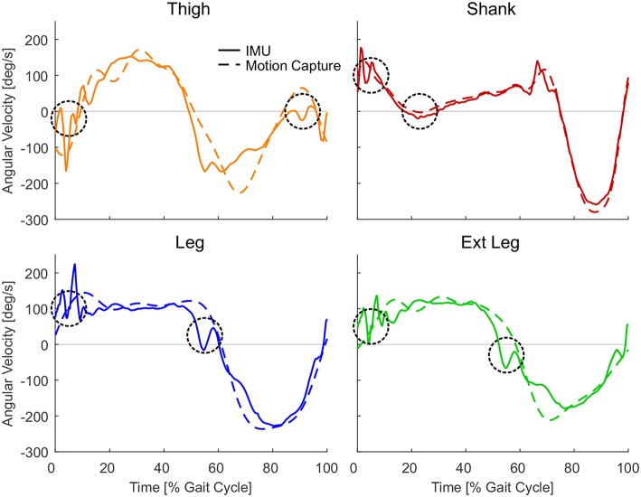
Lower limb exoskeletons require the correct support magnitude and timing to achieve user assistance. This study evaluated whether the sign of the angular velocity of lower limb segments can be used to determine the timing of the stance and the swing phase during walking. We assumed that stance phase is characterized by a positive, swing phase by a negative angular velocity. Thus, the transitions can be used to also identify heel-strike and toe-off. Thirteen subjects without gait impairments walked on a treadmill at speeds between 0.5 and 2.1 m/s on level ground and inclinations between -10 and +10°. Kinematic and kinetic data was measured simultaneously from an optical motion capture system, force plates, and five inertial measurement units (IMUs). These recordings were used to compute the angular velocities of four lower limb segments: two biological (thigh, shank) and two virtual that were geometrical projections of the biological segments (virtual leg, virtual extended leg). We analyzed the reliability (two sign changes of the angular velocity per stride) and the accuracy (offset in timing between sign change and ground reaction force based timing) of the virtual and biological segments for detecting the gait phases stance and swing. The motion capture data revealed that virtual limb segments seem superior to the biological limb segments in the reliability of stance and swing detection. However, increased signal noise when using the IMUs required additional rule sets for reliable stance and swing detection. With IMUs, the biological shank segment had the least variability in accuracy. The IMU-based heel-strike events of the shank and both virtual segment were slightly early (3.3-4.8% of the gait cycle) compared to the ground reaction force-based timing. Toe-off event timing showed more variability (9.0% too early to 7.3% too late) between the segments and changed with walking speed. The results show that the detection of the heel-strike, and thus stance phase, based on IMU angular velocity is possible for different segments when additional rule sets are included. Further work is required to improve the timing accuracy for the toe-off detection (swing).
Keywords: control; detection; exoskeleton; gait phase; inertial measurement unit; stance; swing; walking.
Figures


Similar articles
-
Contributions to the understanding of gait control.Dan Med J. 2014 Apr;61(4):B4823. Dan Med J. 2014. PMID: 24814597 Review.
-
Thigh and Shank, Kinetic and Potential Energies during Gait Swing Phase in Healthy Adults and Stroke Survivors.Brain Sci. 2022 Aug 2;12(8):1026. doi: 10.3390/brainsci12081026. Brain Sci. 2022. PMID: 36009089 Free PMC article.
-
Walking with robot-generated haptic forces in a virtual environment: a new approach to analyze lower limb coordination.J Neuroeng Rehabil. 2021 Sep 9;18(1):136. doi: 10.1186/s12984-021-00823-5. J Neuroeng Rehabil. 2021. PMID: 34503526 Free PMC article.
-
Comparative assessment of heel rise detection for consistent gait phase separation.Heliyon. 2024 Jun 24;10(13):e33546. doi: 10.1016/j.heliyon.2024.e33546. eCollection 2024 Jul 15. Heliyon. 2024. PMID: 39040320 Free PMC article.
-
Analysis of the performance of 17 algorithms from a systematic review: Influence of sensor position, analysed variable and computational approach in gait timing estimation from IMU measurements.Gait Posture. 2018 Oct;66:76-82. doi: 10.1016/j.gaitpost.2018.08.025. Epub 2018 Aug 23. Gait Posture. 2018. PMID: 30170137
Cited by
-
Rules-Based Real-Time Gait Event Detection Algorithm for Lower-Limb Prosthesis Users during Level-Ground and Ramp Walking.Sensors (Basel). 2022 Nov 17;22(22):8888. doi: 10.3390/s22228888. Sensors (Basel). 2022. PMID: 36433483 Free PMC article.
-
Simplified Markerless Stride Detection Pipeline (sMaSDP) for Surface EMG Segmentation.Sensors (Basel). 2023 Apr 27;23(9):4340. doi: 10.3390/s23094340. Sensors (Basel). 2023. PMID: 37177543 Free PMC article.
-
Control strategies used in lower limb exoskeletons for gait rehabilitation after brain injury: a systematic review and analysis of clinical effectiveness.J Neuroeng Rehabil. 2023 Feb 19;20(1):23. doi: 10.1186/s12984-023-01144-5. J Neuroeng Rehabil. 2023. PMID: 36805777 Free PMC article.
-
Enhancing Wearable Gait Monitoring Systems: Identifying Optimal Kinematic Inputs in Typical Adolescents.Sensors (Basel). 2023 Oct 6;23(19):8275. doi: 10.3390/s23198275. Sensors (Basel). 2023. PMID: 37837105 Free PMC article.
-
Learning to walk with a wearable robot in 880 simple steps: a pilot study on motor adaptation.J Neuroeng Rehabil. 2021 Nov 1;18(1):157. doi: 10.1186/s12984-021-00946-9. J Neuroeng Rehabil. 2021. PMID: 34724940 Free PMC article.
References
-
- Alaqtash M., Yu H., Brower R., Abdelgawad A., Sarkodie-Gyan T. (2011). Application of wearable sensors for human gait analysis using fuzzy computational algorithm. Eng. Appl. Artif. Intell. 24, 1018–1025. 10.1016/j.engappai.2011.04.010 - DOI
-
- Arun Jayaraman P. T., Rymer W. Z. (2017). Exoskeletons for rehabilitation and personal mobility: creating clinical evidence,in Wearable Robotics: Challenges and Trends, eds González-Vargas J., Ibáñez J., Contreras-Vidal J. L., van der Kooij H., Pons J. L. (Cham: Springer International Publishing; ), 21–24.
-
- Asbeck A. T., Schmidt K., Galiana I., Wagner D., Walsh C. J. (2015). Multi-joint soft exosuit for gait assistance,in 2015 IEEE International Conference on Robotics and Automation (ICRA) (Seattle, WA: ), 6197–6204.
LinkOut - more resources
Full Text Sources