. 2019 Oct 8;25(56):12966-12980.
doi: 10.1002/chem.201901975. Epub 2019 Sep 18.

Flavylium Salts: A Blooming Core for Bioinspired Ionic Liquid Crystals

Affiliations

Flavylium Salts: A Blooming Core for Bioinspired Ionic Liquid Crystals

Robert Forschner et al. Chemistry. .

Abstract

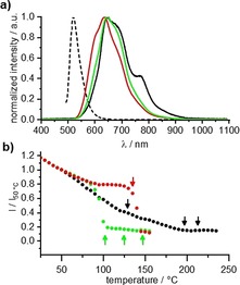
Thermotropic ionic liquid crystals based on the flavylium scaffold have been synthesized and studied for their structure-properties relationship for the first time. The mesogens were probed by differential scanning calorimetry (DSC), polarizing optical microscopy (POM), and X-ray diffraction (XRD). Low numbers of alkoxy side chains resulted in smectic (SmA) and lamello-columnar (LamCol ) phases, whereas higher substituted flavylium salts showed Colro as well as ordered and disordered columnar (Colho , Colhd ) mesophases. Mesophase width ranged from 13 K to 220 K, giving access to room temperature liquid crystals. The optical properties of the synthesized compounds were probed towards absorption and emission properties. Strong absorption with maxima between 444 and 507 nm was observed, and some chromophores were highly emissive with quantum yields up to 99 %. Ultimately, mesogenic and dye properties were examined by temperature-dependent emissive experiments in the solid state.

Keywords: UV/Vis spectroscopy; X-ray diffraction; fluorescence; ionic liquid crystals; self-assembly.


Conflict of interest statement

The authors declare no conflict of interest.

Figures

Scheme 1
Scheme 1
Examples of liquid crystalline oxonium salts reported in the literature and the basic structure of the flavylium salts A‐Fla‐B.
Scheme 2
Scheme 2
i) C12H25Br, K2CO3, DMF, 80 °C, 3 h; ii) 1. C12H25Br, K2CO3, NaI, CH3CN, 105 °C, 2 d; 2. LiAlH4, Et2O, RT, 1 h; 3. DDQ, 1,4‐dioxane, RT, 1 h; iii) H2O2, H2SO4, CHCl3, CH3OH, RT, 18 h; iv) ethynylmagnesium bromide, THF, RT, 3 h; v) IBX, EtOAc, 80 °C, 18 h.
Scheme 3
Scheme 3
Molecular structures of the flavylium salts A‐Fla‐B prepared in this work.
Figure 1
Figure 1
Single‐crystal Xray structure representations of V‐Fla‐1 in the solid state31 (H=light blue, C=white, O=red, S=yellow, F=green, in b) and c) hydrogens are omitted for clarity). a) Hydrogen‐bond interactions of the triflate anion given by dashed lines. b) Stacking interaction of the flavylium cation. c) bc view along the a axis showing the interdigitated layer structure.
Figure 2
Figure 2
Overview of the observed mesophase of the flavylium salts A‐Fla‐B (a detailed version of this diagram with the mesophase width can be found in Figure S1, Supporting Information).
Figure 3
Figure 3
POM micrographs of a) V‐Fla‐1 at 205 °C (magnification 200×) and b) at 188 °C (magnification 100×). All pictures were taken between crossed polarizers upon cooling from the isotropic phase with a cooling rate of 5 K min−1.
Figure 4
Figure 4
Diffractogram and the diffraction pattern of the oriented sample of V‐Fla‐1 in the a) SmA phase at 210 °C and b) LamCol phase at 170 °C after cooling from the isotropic state (cooling rate: 5 K min−1). c) 2D SAXS pattern of the LamCol mesophase and the χ‐scan of the diffraction peaks obtained by slow cooling (0.2 K min−1) from the SmA phase into the LamCol phase. d) Proposed packing of the molecules in the LamCol mesophase. e) Temperature dependent layer spacing of the (001) reflex (▪), the (002) reflex (•) and the (010) reflex (▴) in the SmA (hollow symbols) and the LamCol phase (filled symbols) of compound V‐Fla‐1. The measurement was performed via the second heating (rate: 2 K min−1).
Figure 5
Figure 5
Polarized optical micrographs of a) 2‐Fla‐1 at 135 °C (magnification 100x) upon heating, b) 2‐Fla‐1 at 115 °C (magnification 100x) upon cooling from the isotropic liquid, c) fan‐shaped textures at 135 °C and at d) 110 °C. 2‐Fla‐1 in a rubbed polyimide cell (homogeneous alignment, cell gap: 3 μm) upon cooling. 2‐Fla‐1 in a single side rubbed nylon cell, cell gap: 1.6 μm) at e) 135 °C and f) 110 °C.
Figure 6
Figure 6
a) SAXS and b) WAXS patterns of 2‐Fla‐1 at 130 °C, 120 °C and 90 °C (from top to bottom). b) Temperature dependent layer spacing of the 001 and 002 reflex on cooling from the isotropic state. Transition temperatures are given by the dashed lines. c) Temperature‐dependent layer spacing of the (001) reflex (▪) and the (002) reflex (•) in the LamCol phase (filled symbols), the SmA′ phase (gray symbols) and the SmA phase (hollow symbols).
Figure 7
Figure 7
Polarized optical micrographs of a) iV‐Fla‐2 at 196 °C (magnification 200×) and b) iV‐Fla‐3 at 120 °C (magnification 200×). All pictures were taken by cooling from the isotropic phase with a cooling rate of 5 K min−1.
Figure 8
Figure 8
X‐ray diffractograms of a fiber sample of a) iV‐Fla‐2 at 110 °C and b) iV‐Fla‐3 at 120 °C with the corresponding 2D diffraction pattern with the azimuthal angles of the diffuse wide‐angle reflexes. The fitting of the wide‐angle area is given in grey with the sum (bold line) of the distinct Gauss peaks (dashed lines). White arrows indicate the direction of the fiber. c) Proposed packing model of the Colro phase and the stacking within the column (the representation of the discoid has been simplified, for a more detailed discussion see Figure 10 and the corresponding text).
Figure 9
Figure 9
Polarized optical micrographs of V‐Fla‐3 at a) 125 °C (inset: dendritic germ observed below the clearing point, picture taken with slightly uncrossed polarizers) and b) 75 °C between crossed polarizers. Textures of 2‐Fla‐3 at c) 185 °C and d) 75 °C. All pictures were taken by cooling from the isotropic phase with a cooling rate of 5 K min−1 and a magnification of 200×.
Figure 10
Figure 10
Proposed packing model of the flavylium salts in the a) Colho and the b) Colro mesophase viewed from the top (left) and in an side view (right).The flavylium cations are displayed as blue arrows (pointing towards the oxonium cation) and the triflate anions as red dots.
Figure 11
Figure 11
a) WAXS diffractogram of 3‐Fla‐1 at 85 °C. The inset displays the SAXS pattern of a planar aligned domain obtained by slow heating into the Colh phase at 80 °C (the additional diffuse reflex is most likely due passing of the beam through another domain without mesophase). b) Proposed stacking of two flavylium cations V‐Fla‐3 in the liquid crystalline state.
Figure 12
Figure 12
a) Absorption spectra (bold line, represented by its extinction coefficient determined by linear regression of a concentration series ranging from 0.2×10⁻⁵m to 7×10⁻⁵m) and normalized emission spectra (dashed line) of vanillin‐derived flavylium salts V‐Fla‐B in CHCl3. Solutions of the corresponding flavylium salt under b) daylight and c) UV‐radiation (366 nm).
Figure 13
Figure 13
a) Emission spectra of V‐Fla‐1 (black), iV‐Fla‐1 (red) and 2‐Fla‐1 (green) in the solid state at 50 °C under irradiation with UV light (350–380 nm, solution spectra of V‐Fla‐1 is given in dashed lines for comparison) and b) temperature‐dependent emission intensity at 665 nm upon cooling the sample from the isotropic liquid (cooling rate of 10 K min−1). For the orientation transition temperatures of the DSC are given as arrows.
Figure 14
Figure 14
Optical micrographs of V‐Fla‐1 observed between crossed polarizers (left column) and under UV radiation (right column, without polarizer, exposure time: 8 seconds, the brightness of b) and d) has been increased by 40 % to ensure visibility) in the a–b) isotropic phase at 230 °C, c‐d) the SmA phase at 200 °C, e–f) the LamCol phase at 170 °C and g–h) the crystalline phase at 30 °C. The images were obtained by cooling of the isotropic liquid with a cooling rate of 10 K min−1.

Similar articles

Cited by

References

    1. Binnemans K., Chem. Rev. 2005, 105, 4148–4204. - PubMed
    1. Goossens K., Lava K., Bielawski C. W., Binnemans K., Chem. Rev. 2016, 116, 4643–4807. - PubMed
    1. Handbook of Liquid Crystals (Eds.: J W. Goodby, C. Tschierske, P. Raynes, H. Gleeson, T. Kato, P. J. Collings), Wiley-VCH, Weinheim, 2014.
    1. Axenov K. V., Laschat S., Materials 2011, 4, 206–259. - PMC - PubMed
    1. Chen S., Eichhorn S. H., Isr. J. Chem. 2012, 52, 830–843.