. 2019 Aug 16;10(1):3706.
doi: 10.1038/s41467-019-11717-5.

Strong light-matter coupling for reduced photon energy losses in organic photovoltaics

Affiliations

Strong light-matter coupling for reduced photon energy losses in organic photovoltaics

Vasileios C Nikolis et al. Nat Commun. .

Abstract

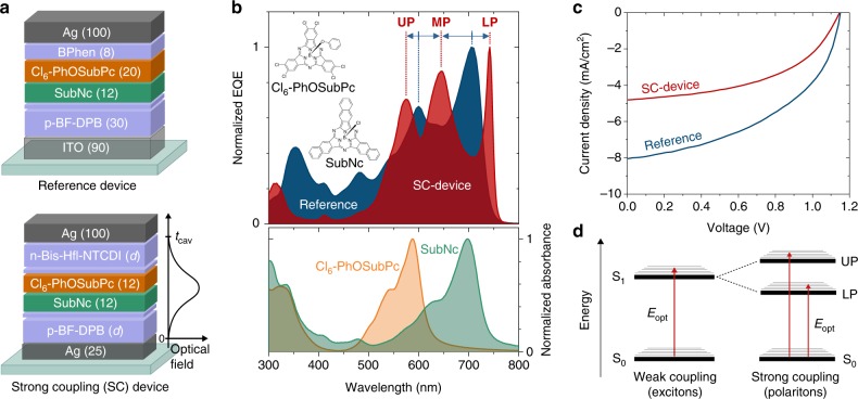
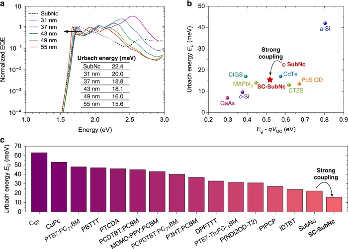
Strong light-matter coupling can re-arrange the exciton energies in organic semiconductors. Here, we exploit strong coupling by embedding a fullerene-free organic solar cell (OSC) photo-active layer into an optical microcavity, leading to the formation of polariton peaks and a red-shift of the optical gap. At the same time, the open-circuit voltage of the device remains unaffected. This leads to reduced photon energy losses for the low-energy polaritons and a steepening of the absorption edge. While strong coupling reduces the optical gap, the energy of the charge-transfer state is not affected for large driving force donor-acceptor systems. Interestingly, this implies that strong coupling can be exploited in OSCs to reduce the driving force for electron transfer, without chemical or microstructural modifications of the photo-active layer. Our work demonstrates that the processes determining voltage losses in OSCs can now be tuned, and reduced to unprecedented values, simply by manipulating the device architecture.


Conflict of interest statement

The authors declare no competing interests.

Figures

Fig. 1
Fig. 1
Effects of strong coupling (SC) on the performance of SubNc/Cl6-PhOSubPc organic solar cells. a Device structure of a normal SubNc/Cl6-PhOSubPc solar cell employing ITO as bottom contact used as reference, and general device structure of solar cells exhibiting SC effects. For the SC-devices, the thickness d of the n-doped electron transport layer and p-doped hole transport layer are kept the same. b Normalized EQE spectra (upper panel) of the reference and an exemplary SC-device (with d = 55 nm) demonstrating the splitting of the absorption peaks of SubNc and Cl6-PhOSubPc (lower panel). The blue solid arrows indicate splitting of the absorption peaks of both materials into upper-polariton, middle-polariton, and lower-polariton (UP, MP, and LP, respectively). As a result, the EQE spectrum of the SC-device is redshifted and its low-energy edge steepened. Inset pictures show the molecular structures of SubNc and Cl6-PhOSubPc. c Current–voltage characteristic curves of the reference and SC-device show that the VOC remains rather constant under SC. d Excited-state diagram illustrating the splitting of the first singlet excited state (S1) into two polariton states. Electronic transitions (red arrows) can occur directly from the ground state (S0) to the high-energy upper polariton (UP) and the low-energy lower polariton (LP). The energetically lower LP defines the optical gap (Eopt) of the polariton based solar cell
Fig. 2
Fig. 2
Thickness-dependent EQE and EL of SubNc/Cl6-PhOSubPc-based devices under strong coupling. a EQE (upper panel) and normalized electroluminescence (EL) spectra (lower panel) of five SC-devices, for different transport layers’ thickness d, showing the redshift of the device’s absorption and emission for increasing d. Different values of d lead to different cavity lengths and resonance wavelengths for the cavity photons. The five devices were exemplarily selected for the investigated range d, and the full series of devices is shown in Supplementary Fig. 2. b Simulated photoactive absorption (false color) in cells with varying d showing the formation of polariton branches with pronounced anti-crossing at overlapping points of the cavity and exciton resonances (dashed lines). The simulation results agree well with the calculated polariton branches (solid lines) of a coupled oscillator model and the experimental EQE data (red squares). c Comparison between EQE and EL peaks of the LP peak for various d. The colored numbers (in nm and meV) denote the Stokes shift in each case. The minimal Stokes shifts confirm that the investigated devices operate in the strong coupling regime
Fig. 3
Fig. 3
Effects of strong coupling on EQE and electroluminescence of SubNc/C60 based cells. a EQE spectra for strongly coupled SubNc/C60 solar cells, for varying transport layer thickness d. EQE of a reference solar cell utilizing only SubNc (‘SubNc’, black) is included for comparison. In the strongly coupled devices, the SubNc peak is split into two polariton peaks which redshift for increasing d. b Sensitively measured normalized reduced EQE and EL spectra of the same devices. The low-energy EQE and high-energy EL edges of the most blue-shifted and red-shifted spectra are fitted (purple and red dashed lines, respectively) and the crossing point of their Gaussian lineshapes (purple and red dotted lines) provide the CT-state energy in each case
Fig. 4
Fig. 4
Voltage and energy losses of SubNc/C60 SC-devices with varying transport layer thickness d. The Eopt of the devices corresponds to the peak of the LP branch λpeak (Fig. 3a), and ECT is determined from the crossing point between appropriately normalized reduced EQE and EL spectra (Fig. 3b), which is found to be approximately the same for the investigated devices. With increasing transport layer thickness, the driving force (EoptECT) and the total energy losses (EoptqVOC) decrease. ΔVrad and ΔVnonrad correspond to the voltage losses related to radiative and non-radiative recombination, respectively, and remain rather unaffected by strong coupling
Fig. 5
Fig. 5
Steepening the absorption edge for reduced photon energy losses with strong coupling. a Sensitively measured EQE spectra of the investigated SubNc/Cl6-PhOSubPc based SC-devices for various transport layer thicknesses d, including the reference solar cell employing only SubNc (‘SubNc’). Increasing d red-shifts the device absorption, steepening the absorption edge. b Urbach energy (EU) versus EgqVOC losses for the SubNc/Cl6-PhOSubPc based SC-device (‘SC-SubNc’), exhibiting the EU = 15.6 meV and energy losses of 0.525 eV, and record solar cells of other inorganic photovoltaic technologies. The reference SubNc/Cl6-PhOSubPc device (‘SubNc’) is also included to demonstrate how strong coupling reduces both EU and photon energy losses. Adapted by De Wolf et al. and Jean et al. . c EU values for various organic photovoltaic materials and blends. The value of 15.6 meV for the ‘SC-SubNc’ device is the lowest for organic materials. Values of materials and blends, which were not investigated in this work, were taken from literature,–

References

    1. Xu X, et al. Single‐junction polymer solar cells with 16.35% efficiency enabled by a Platinum(II) complexation strategy. Adv. Mater. 2019;31:1901872. doi: 10.1002/adma.201901872. - DOI - PubMed
    1. Cui Y, et al. Over 16% efficiency organic photovoltaic cells enabled by a chlorinated acceptor with increased open-circuit voltages. Nat. Commun. 2019;10:2515. doi: 10.1038/s41467-019-10351-5. - DOI - PMC - PubMed
    1. Meng L, et al. Organic and solution-processed tandem solar cells with 17.3% efficiency. Science. 2018;361:1094–1098. doi: 10.1126/science.aat2612. - DOI - PubMed
    1. Nikolis Vasileios C., Benduhn Johannes, Holzmueller Felix, Piersimoni Fortunato, Lau Matthias, Zeika Olaf, Neher Dieter, Koerner Christian, Spoltore Donato, Vandewal Koen. Reducing Voltage Losses in Cascade Organic Solar Cells while Maintaining High External Quantum Efficiencies. Advanced Energy Materials. 2017;7(21):1700855. doi: 10.1002/aenm.201700855. - DOI
    1. Benduhn J, et al. Intrinsic non-radiative voltage losses in fullerene-based organic solar cells. Nat. Energy. 2017;2:17053. doi: 10.1038/nenergy.2017.53. - DOI