

An azimuthally-modified linear phase grating: Generation of varied radial carpet beams over different diffraction orders with controlled intensity sharing among the generated beams
- PMID: 31462671
- PMCID: PMC6713793
- DOI: 10.1038/s41598-019-48757-2
An azimuthally-modified linear phase grating: Generation of varied radial carpet beams over different diffraction orders with controlled intensity sharing among the generated beams
Abstract
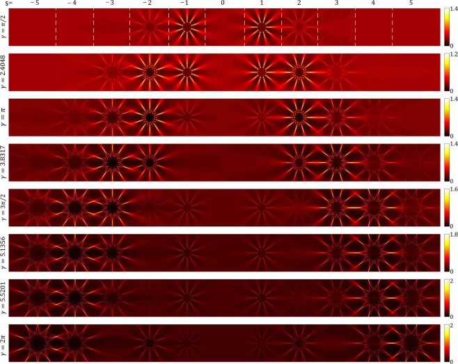
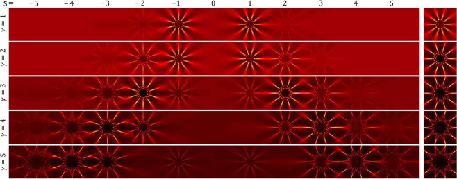
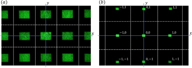
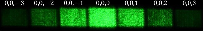
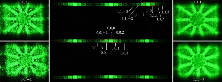
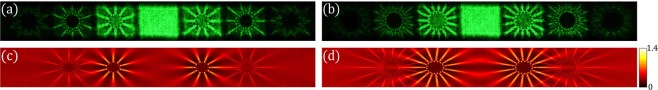
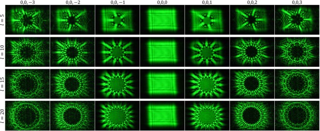
Diffraction gratings are important optical components and are used in many areas of optics such as in spectroscopy. A diffraction grating is a periodic structure that splits and diffracts the impinging light beam into several beams travelling in different directions. The diffracted beams from a grating are commonly called diffraction orders. The directions of the diffraction orders depend on the grating period and the wavelength of the impinging light beam so that a grating can be used as a dispersive element. In the diffraction of a plane wave from a conventional grating, the intensities of diffracted beams decrease with increasing order of diffraction. Here, we introduce a new type of grating where in the diffraction of a plane wave, the intensity of a given higher order diffracted beam can be higher than the intensity of the lower orders. We construct these gratings by adding an azimuthal periodic dependency to the argument of the transmission function of a linear phase grating that has a sinusoidal profile and we call them azimuthally-modified linear phase gratings (AMLPGs). In this work, in addition to introducing AMLPGs, we present the generation of varied radial carpet beams over different diffraction orders of an AMLPG with controlled intensity sharing among the generated beams. A radial carpet beam is generated in the diffraction of a plane wave from a radial phase grating. We show that for a given value of the phase amplitude over the host linear phase grating, one of the diffraction orders is predominant and by increasing the value of the phase amplitude, the intensity sharing changes in favor of the higher orders. The theory of the work and experimental results are presented. In comparison with the diffraction of a plane wave from radial phase gratings, the use of AMLPGs provides high contrast diffraction patterns and presents varied radial carpet beams over the different diffraction orders of the host linear phase grating. The resulting patterns over different diffraction orders are specified and their differences are determined. The diffraction grating introduced with controlled intensity sharing among different diffraction orders might find wide applications in many areas of optics such as optical switches. We show that AMLPG-based radial carpet beams can be engineered in which they acquire sheet-like spokes. This feature nominates them for potential applications in light sheet microscopy. In addition, a detailed analysis of the multiplication of the diffraction pattern of an AMLPG by the 2D structure of a spatial light modulator is presented. The presented theory is confirmed by respective experiments.
Conflict of interest statement
The authors declare no competing interests.
Figures

Similar articles
-
Gaussian beam diffraction from radial structures: detailed study on the diffraction from sinusoidal amplitude radial gratings.Opt Express. 2023 Jun 19;31(13):20665-20682. doi: 10.1364/OE.489659. Opt Express. 2023. PMID: 37381185
-
Theory and generation of heterogeneous 2D arrays of optical vortices by using 2D fork-shaped gratings: topological charge and power sharing management.Opt Express. 2023 May 8;31(10):16361-16379. doi: 10.1364/OE.487501. Opt Express. 2023. PMID: 37157716
-
Gear-like rotatable optical trapping with radial carpet beams.Sci Rep. 2020 Jul 16;10(1):11721. doi: 10.1038/s41598-020-68695-8. Sci Rep. 2020. PMID: 32678205 Free PMC article.
-
Robustness of highly complex radial carpet beams in turbulent atmospheres.Sci Rep. 2024 Aug 8;14(1):18419. doi: 10.1038/s41598-024-69443-y. Sci Rep. 2024. PMID: 39117756 Free PMC article.
-
Dynamic Control of Light Direction Enabled by Stimuli-Responsive Liquid Crystal Gratings.Adv Mater. 2019 Feb;31(7):e1806172. doi: 10.1002/adma.201806172. Epub 2018 Dec 20. Adv Mater. 2019. PMID: 30570775 Review.
Cited by
-
Voltage-controlled two-dimensional Fresnel diffraction pattern in quantum dot molecules.Sci Rep. 2024 Mar 9;14(1):5815. doi: 10.1038/s41598-024-55204-4. Sci Rep. 2024. PMID: 38461176 Free PMC article.
References
-
- Talbot HF. Lxxvi. facts relating to optical science. no. iv. Philos. Mag. 1836;9(56):401–407.
-
- Patorski, K. & Kujawinska, M. Handbook of the moiré fringe technique (Elsevier Science, 1993).
-
- Rasouli S, Sakha F, Yeganeh M. Infinite–mode double-grating interferometer for investigating thermal–lens–acting fluid dynamics. Meas. Sci. Technol. 2018;29:085201. doi: 10.1088/1361-6501/aacab3. - DOI
LinkOut - more resources
Full Text Sources
Miscellaneous
