. 2019 Nov 15:202:116124.
doi: 10.1016/j.neuroimage.2019.116124. Epub 2019 Aug 29.

Prospects for transcranial temporal interference stimulation in humans: A computational study

Affiliations

Prospects for transcranial temporal interference stimulation in humans: A computational study

Sumientra Rampersad et al. Neuroimage. .

Abstract

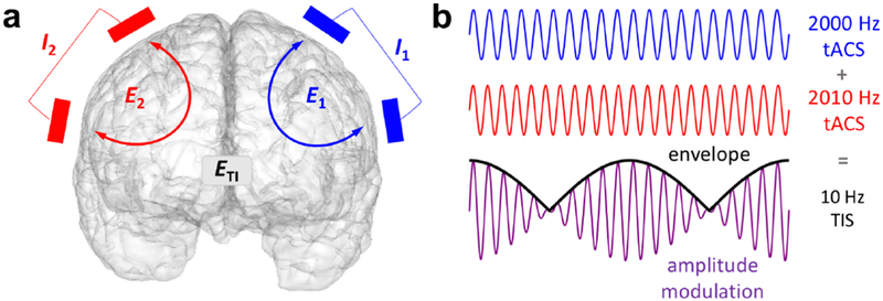
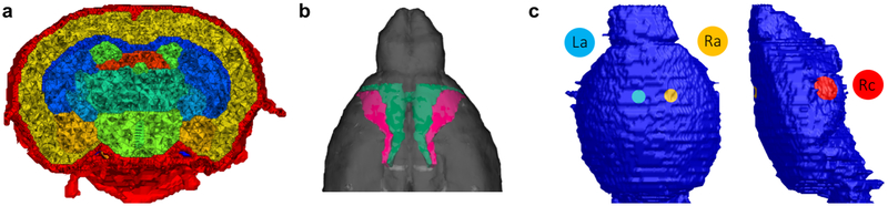
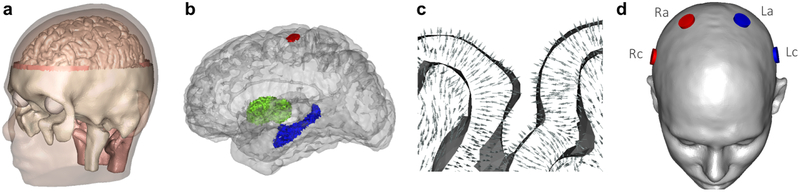
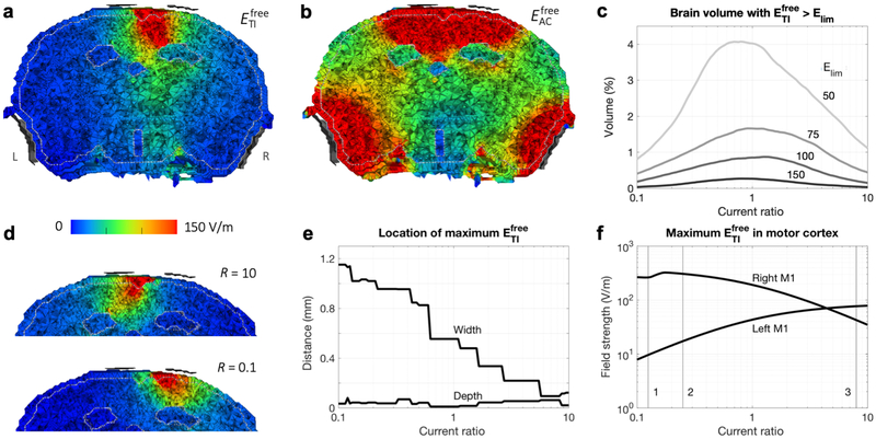
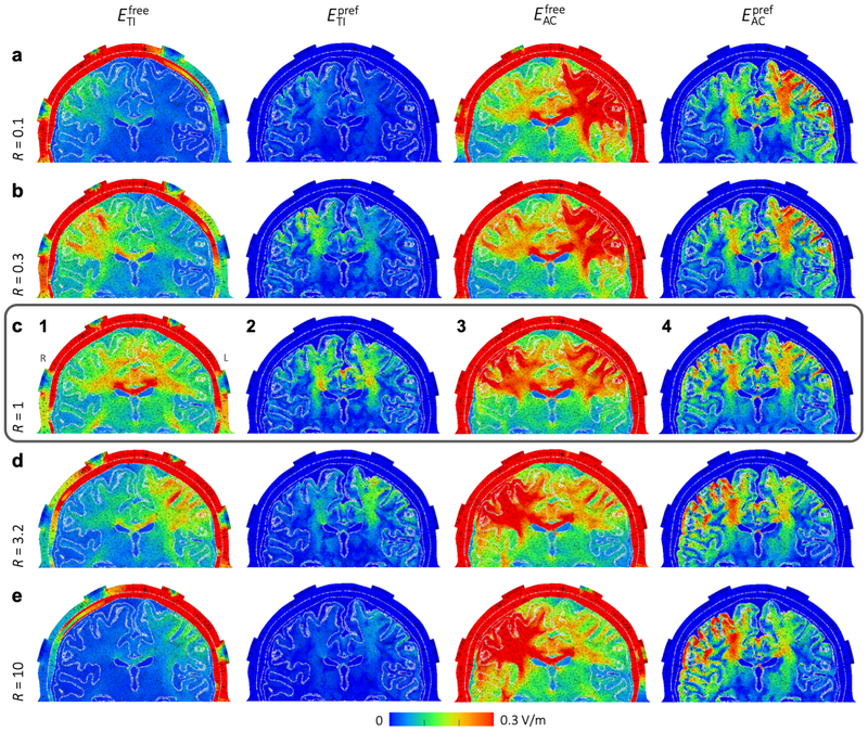
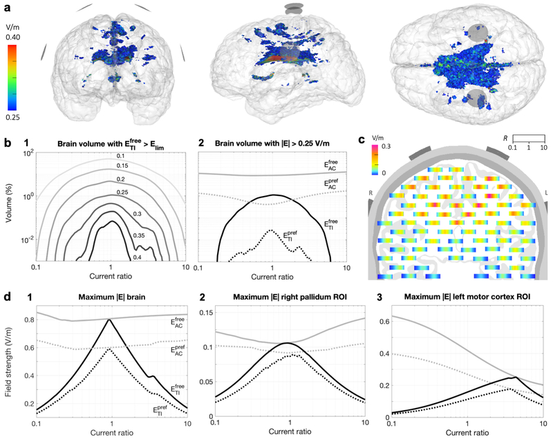
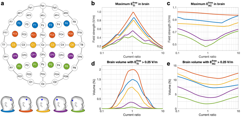
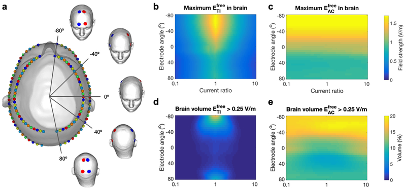
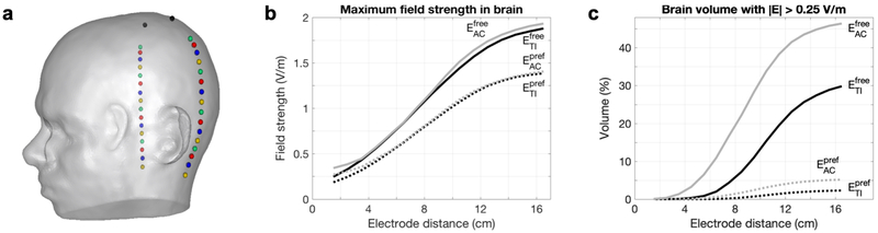
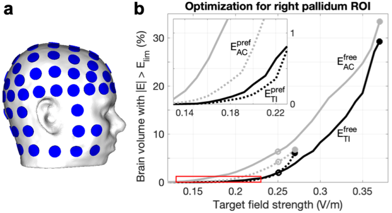
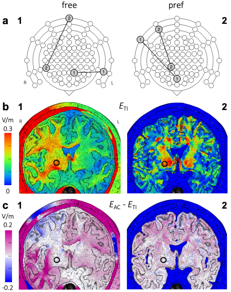
Transcranial alternating current stimulation (tACS) is a noninvasive method used to modulate activity of superficial brain regions. Deeper and more steerable stimulation could potentially be achieved using transcranial temporal interference stimulation (tTIS): two high-frequency alternating fields interact to produce a wave with an envelope frequency in the range thought to modulate neural activity. Promising initial results have been reported for experiments with mice. In this study we aim to better understand the electric fields produced with tTIS and examine its prospects in humans through simulations with murine and human head models. A murine head finite element model was used to simulate previously published experiments of tTIS in mice. With a total current of 0.776 mA, tTIS electric field strengths up to 383 V/m were reached in the modeled mouse brain, affirming experimental results indicating that suprathreshold stimulation is possible in mice. Using a detailed anisotropic human head model, tTIS was simulated with systematically varied electrode configurations and input currents to investigate how these parameters influence the electric fields. An exhaustive search with 88 electrode locations covering the entire head (146M current patterns) was employed to optimize tTIS for target field strength and focality. In all analyses, we investigated maximal effects and effects along the predominant orientation of local neurons. Our results showed that it was possible to steer the peak tTIS field by manipulating the relative strength of the two input fields. Deep brain areas received field strengths similar to conventional tACS, but with less stimulation in superficial areas. Maximum field strengths in the human model were much lower than in the murine model, too low to expect direct stimulation effects. While field strengths from tACS were slightly higher, our results suggest that tTIS is capable of producing more focal fields and allows for better steerability. Finally, we present optimal four-electrode current patterns to maximize tTIS in regions of the pallidum (0.37 V/m), hippocampus (0.24 V/m) and motor cortex (0.57 V/m).

Keywords: Bioelectricity simulation; Finite element modeling (FEM); Non-invasive brain stimulation; Optimization; Temporal interference; Transcranial alternating current stimulation (tACS).


Figures

Figure 1:
Figure 1:. Concept of temporal interference stimulation.
a) Example arrangement of the two pairs of stimulating electrodes on the scalp, each supplying an oscillating current and producing an oscillating electric field. The intersection of the two fields produces an amplitude-modulated field ETI. Note that it is not required for the two sets of electrodes to be on opposite sides of the head. b) Illustration of two high-frequency oscillations and their sum, which is an amplitude-modulated oscillation with a carrier frequency equal to the average frequency of the inputs and an envelope oscillating at the difference frequency.
Figure 2:
Figure 2:. Murine model.
a) Cut through the finite element model, showing the skull (red), CSF (green), cortex (yellow) and various deeper brain regions. b) Location of the left and right primary motor cortex (pink) in the model. c) Electrodes on the skull surface of the model, placed based on experiments performed by Grossman et al. (2017) (the left cathode eLc is not visible here; it is placed symmetrically to eRc).
Figure 3:
Figure 3:. Human head model.
a) Geometry of the model. b) Location of the three selected brain structures: left hippocampus (blue), right pallidum (green) and FDI area of left motor cortex (red). c) Section of gray and white matter with arrows representing the preferred direction vectors npref. See Fig. S2b for an image of npref in the whole brain. d) Electrodes on the skin surface of the model. Each simulated configuration in Studies 1 and 2 consisted of two electrodes on the left side of the head (blue) that supplied current I1 and two on the right (red) that supplied I2. The configuration shown here is the standardized configuration used in Study 1 with electrodes at the C1, C2, C5 and C6 locations of the 10-10 system.
Figure 4:
Figure 4:. Results of simulations with the murine model.
a,b) IL = IR = 0.388 mA. Electric field strength on a plane through the electrodes (viewing towards the anterior direction; L and R in panel a indicate the left and right side of the head for all panels) for tTIS (a) and tACS (b). Maxima in the brain were 383 V/m for ETIfree and 38 kV/m for EACfree. The four electrodes (gray) were displayed at a short distance from the head for visualization purposes. The distinct areas with low field strengths are the ventricles. c-f) Current ratios R = IR/IL varied from 0.1 to 10 with IL + IR = 0.776 mA. c) Percentage of brain tissue with ETIfree above various limits (limit values indicated in the plot in V/m; total brain volume: 465 mm3). d) ETIfree for extreme values of R (compare to R = 1 in panel a). See Fig. S2 for corresponding animations with intermediate R for tTIS and tACS. e) Distance of the location of maximum ETIfree in the brain to the midline (“width”, positive values indicate a location to the right of the midline) and skull surface (“depth”). Lines are not smooth due to the finite size of elements in the model. f) Maximum ETIfree in left and right motor cortex. Numbered lines indicate ratios that elicited the largest movements in the Grossman et al. (2017) experiments for 1: left forepaw; 2: left whiskers; 3: right forepaw and right whiskers.
Figure 5:
Figure 5:. Study 1 – Field strength distributions for tTIS and tACS with various current ratios.
Field strengths are displayed on a plane through the electrodes (all placed in the coronal plane), viewing towards the posterior direction (L and R in panel c1 indicate the left and right side of the head for all panels). From top to bottom, the current ratio R = IR/IL is increased from 0.1 to 10. Equal current amplitudes, R = 1, are shown in the middle row, indicated with a surrounding box. From left to right, ETIfree, ETIpref, EACfree and EACpref are displayed. Since the preferred direction is only defined for brain elements, all non-brain elements have a value of 0 for plots of ETIpref and EACpref. Note that since we are displaying electric field strength, values will be high in areas with low conductivity (such as the skull) and low for highly conductive regions. See Fig. S3 for corresponding animations for intermediate current ratios, and Fig. S1 for visualizations of the directions of EL, ER, ETIfree, EACfree and npref.
Figure 6:
Figure 6:. Study 1 – Stimulated brain volumes and maximal field strengths for tTIS and tACS.
a) Brain volume for which ETIfree > 0.25 V/m for a simulation with IL = IR = 1 mA, visualized from the front, left and top, respectively; images are all on the same scale. Electrode surfaces are visualized as gray disks. See Fig. S4 for corresponding animations for other current ratios and other Elim values for tTIS and tACS. b-d) Results for simulations with current ratios R = IR/IL varied from 0.1 to 10 with IL + IR = 2 mA. b) Percentage of brain volume for which 1) ETIfree surpasses various limits (values indicated in the plot in V/m), or 2) field strengths surpass 0.25 V/m, for tTIS (black) and tACS (gray) in either a free (continuous lines) or preferred direction (dotted lines). c) On a plane through the electrodes, viewing towards the posterior direction (L and R indicate left and right side of the head), each bar displays the local ETIfree for all current ratios, where horizontal position within each individual bar corresponds to R ranging from 0.1 on the left to 10 on the right. d) Maximum field strength in the entire brain (1), and in small regions of interest (ROIs) in the right pallidum (2) and left motor cortex (3).
Figure 7:
Figure 7:. Study 2a – Simulations of tTIS and tACS with five standardized electrode configurations and various current ratios.
a) Schematic of the 10-10 system with the five configurations marked in different colors (top) and side view of the five head models (bottom). b,c) Maximum field strength in the brain, and d,e) percentage of brain volume stimulated at > 0.25 V/m for ETIfree (b,d) and EACfree (c,e). Line colors match the schematic and models shown in panel a. See Fig. S5 for animations of stimulated brain volumes (similar to Fig. 6a) for tTIS and tACS for all configurations and current ratios.
Figure 8:
Figure 8:. Study 2b – Simulations of tTIS and tACS with a densely sampled set of parallel electrode configurations and various current ratios.
a) Visualization of the design of the 33 configurations on the head model with five configurations highlighted (red: IL; blue: IR). On a top view of the head model, each configuration is represented by four identically colored spheres. The four electrodes of one configuration were placed symmetrically around the midline with equal angles to the coronal plane; the set of four was moved from anterior to posterior by varying the angle between the electrode locations and the coronal plane from −80 to 80 degrees. b,c) Maximum field strength in the brain, and d,e) percentage of brain volume stimulated above 0.25 V/m for ETIfree (b,d) and EACfree (c,e). Results are displayed on a 2D plot with ratio R on the horizontal axis and coronal plane angle in degrees on the vertical axis. See Fig. S7 for animations of stimulated brain volumes (as in Fig. 6a) for tTIS and tACS for all configurations.
Figure 9:
Figure 9:. Study 2c – Simulations of tTIS and tACS with electrode locations varied vertically across the head surface.
a) Visualization of the design of the 16 configurations on the head model. Each configuration consisted of the same two top electrodes (black spheres) and one pair of bottom electrodes (identically colored spheres) placed underneath. b) Maximum field strength in the brain, and c) percentage of brain volume with field strengths above 0.25 V/m, for tTIS (black) and tACS (gray) in either a free (continuous lines) or preferred (dotted lines) direction. See Fig. S8 for animations of tTIS field strength distributions (as in Fig. 5) and stimulated volumes in the brain (as in Fig. 6a) for all configurations.
Figure 10:
Figure 10:. Study 3 – Pareto boundaries of optimal field strength and focality for four-electrode tTIS and tACS in the right pallidum.
a) A set of 88 electrodes was used to perform an exhaustive search optimization over 146M current patterns. b) From this set, these lines present the minimum unwanted stimulation (volume of brain tissue stimulated over 0.25 V/m, Vol0.25) achievable as a function of median field strength in the target region of interest (ROI, EROI), for tTIS (black) and tACS (gray) in either a free (continuous lines) or preferred (dotted lines) direction. From these lines, the most suitable current pattern can be selected to achieve a specific experimental goal. Circles indicate current patterns that minimized Vol0.25 while either maximizing EROI (filled) or reaching at least 0.25 V/m in the ROI (open); more detailed results for these current patterns can be found in Table 2 and Fig. 11. The red box indicates the location of the inset.
Figure 11:
Figure 11:. Study 3 – Optimal current patterns and electric fields for four-electrode tTIS and tACS in the right pallidum.
a) Current patterns that minimized the stimulated brain volume (Vol0.25) while reaching a field strength of at least 0.25 V/m in a spherical ROI in the right pallidum for tTIS in a free (1) or preferred direction (2). Each electrode pair was represented by a line connecting two circles on an extended schematic of the 10-10 system; three rings were added around the standard schematic (Fig. 7a) to represent electrodes on the neck and cheeks (Fig. 10a) and the schematic was rotated 180 degrees to aid interpretation of panel b. For both current patterns, the input currents of each pair were equal (I2 = I1, R = 1). b) Optimal ETI (fields resulting from the current patterns in panel a), and c) difference between optimal EAC and optimal ETI, on a plane through the target region (indicated with a circle) for free (1) and preferred (2) directions, viewing towards the posterior direction (L and R in panel b1 indicate the left and right side of the head for all panels). Optimal current patterns for EAC are shown in Fig. S11.

Similar articles

Cited by

References

    1. Akhtari M, Bryant H, Mamelak A, Flynn E, Heller L, Shih J, et al., . Conductivities of three-layer live human skull. Brain Topogr 2002;14(3):151–167. - PubMed
    1. Åström M, Diczfalusy E, Martens H, Wårdell K. Relationship between neural activation and electric field distribution during deep brain stimulation. IEEE Transactions on Biomedical Engineering 2015;62(2):664–672. doi:10.1109/TBME.2014.2363494. - DOI - PubMed
    1. Bikson M, Inoue M, Akiyama H, Deans JK, Fox JE, Miyakawa H, Jefferys JGR. Effects of uniform extracellular dc electric fields on excitability in rat hippocampal slices in vitro. The Journal of Physiology 2004;557(1):175–190. doi:10.1113/jphysiol.2003.055772. - DOI - PMC - PubMed
    1. Brown CC. Electroanesthesia and electrosleep. American Psychologist 1975;30(3):402–10. - PubMed
    1. Brunoni AR, Vanderhasselt MA. Working memory improvement with non-invasive brain stimulation of the dorsolateral prefrontal cortex: A systematic review and meta-analysis. Brain and Cognition 2014;86:1–9. doi:10.1016/j.bandc.2014.01.008. - DOI - PubMed

Publication types