. 2019 Dec;116(12):3253-3268.
doi: 10.1002/bit.27164. Epub 2019 Sep 26.

Dual-chambered membrane bioreactor for coculture of stratified cell populations

Affiliations

Dual-chambered membrane bioreactor for coculture of stratified cell populations

Javier Navarro et al. Biotechnol Bioeng. 2019 Dec.

Abstract

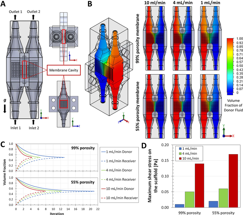
We have developed a dual-chambered bioreactor (DCB) that incorporates a membrane to study stratified 3D cell populations for skin tissue engineering. The DCB provides adjacent flow lines within a common chamber; the inclusion of the membrane regulates flow layering or mixing, which can be exploited to produce layers or gradients of cell populations in the scaffolds. Computational modeling and experimental assays were used to study the transport phenomena within the bioreactor. Molecular transport across the membrane was defined by a balance of convection and diffusion; the symmetry of the system was proven by its bulk convection stability, while the movement of molecules from one flow line to the other is governed by coupled convection-diffusion. This balance allowed the perfusion of two different fluids, with the membrane defining the mixing degree between the two. The bioreactor sustained two adjacent cell populations for 28 days, and was used to induce indirect adipogenic differentiation of mesenchymal stem cells due to molecular cross-talk between the populations. We successfully developed a platform that can study the dermis-hypodermis complex to address limitations in skin tissue engineering. Furthermore, the DCB can be used for other multilayered tissues or the study of communication pathways between cell populations.

Keywords: bioreactor; cellular coculture; membrane; skin; stratified tissues.


Conflict of interest statement

Conflicts of Interest: JN, JS, MJ, MS, AM and JPF declare no conflicts of interest.

Figures

Figure 1.
Figure 1.
DCB design and 3D printing. A) Layered microstructure of human skin and our approach to the development of a simplified layered tissue engineering scaffold. B) Approach to the formation of strata and gradients in a DCB. i) When cultured independently, scaffolds have a single, homogeneous cell population; layering the scaffolds in vivo would result in poor integration and uncontrolled gradient interface. ii) The DCB allows two flow lines of media into a common chamber; without a barrier, the two flows would mix producing a gradient. iii) Inclusion of a membrane in the DCB would keep the flow lines separated producing a stratified construct; permeability of the membrane would regulate transport between the two sides. C) i) The DCB is composed of two equal master pieces that can be sealed together; ii) the master piece is composed of an inlet, an outlet, and an open centerpiece, as well as including guide channels for sealing gaskets; iii-iv) when combined, the cross-section reveals a common chamber that provides an interface for communication between the two flow lines. D-E) The master pieces and custom porous scaffolds for cell culturing were 3D printed on a Perfactory 4 DLP printer (EnvisionTEC) using EShell resin. F) The final DCB system assembled has been optimized to have maximum external dimensions of 64 × 40 × 23 mm (length, width, height), an effective internal volume of 3.8 ml (total volume as seen in Fig. Civ in green, shades distinguish the two halves that compose it), and inlet and outlet connections to standard 1/8” (3.175 mm) inner diameter tubing.
Figure 2.
Figure 2.
CFD modeling of the DCB membrane system. A) CAD model for the proposed DCB system with porous scaffolds inserted in the line chambers, detailing the position of the inlets (1 and 2) and the outlets (1 and 2) and the orientation with respect to gravity; the membrane cavity houses the barrier between the two lines. B) Resulting heat maps of the volume fraction of Donor Fluid (red) and Receiver Fluid (blue), both with the identical properties of water, within the DCB for combinations of membrane porosity (55 or 99%) and inlet flow rate (1, 4, or 10 ml/min). Once stable, the simulations indicate different profiles of mixing at the interface of the two flow lines and the membrane. C) The volume fractions for Donor and Receiver Fluids at every normalized iteration point (proportional to time) were plotted to create mixing profiles as functions of porosity and flow rate; these profiles indicate the point in time, relative to the other cases, were the DCB systems reach concentration equilibrium (complete mixing defined as the point with 50±1% Donor Fluid and 50±1% Receiver Fluid). The inclusion of a membrane in the system dilates the time required for the looped system to reach equilibrium, at all follow rates simulated. D) CFD simulations were used to calculate the maximum shear stress on the surface of the scaffolds (local mesh); decreased porosity increases the resistance within the system and causes regions or points with higher shear stress as flow rate increases. These stress values allowed us to select adequate flow rates for subsequent experiments in the DCB that involve cells growing within the chambers.
Figure 3.
Figure 3.
Assessment of diffusion in the DCB. A) UV-crosslinked keratin membranes casted in custom 3D printed molds. B) DCB master parts ready for assembly, highlighting the inclusion of the keratin membrane and the silicone sealing gaskets. C) For the assessment of diffusion in the DCB inlets and outlets were clamped shut, and sampling ports (red arrows) were opened on each side and sealed with casted paraffin plugs as needed. This system was used to quantify diffusion of model molecules tartrazine and brilliant blue from a donor chamber to a receiver chamber either without an intermediate membrane (D), with a LCD membrane, or with a HCD membrane (E-F) D) Without a membrane, diffusion quickly equilibrates the common chamber, with no significant difference between the concentration of the donor and the receiver chambers by 10 min, for both molecules tracked (n=4). E-F) The inclusion of the membrane significantly delays the equilibrium of the system; equilibrium for both tartrazine (534 Da) and brilliant blue (793 Da) takes at least 6105 min using a LCD membrane (n=4) and 4770 min using a HCD membrane (n=5). Tartrazine reaches equilibrium close to 0.5 (normalized concentration) between donor and receiver, but brilliant blue, which is 33% larger, is significantly and consistently stable around 0.8. G) The permeability of the system was around 2×10⁻⁴ cm2/s with no significant difference between the combinations of molecules and membrane CD. H-I) The keratin membranes recovered from the chambers showed differences between the low and high CD groups; LCD membranes were fully or partially dissolved, while the HCD samples were in considerable better state with some complete samples even after 8d. For all plots, statistical significance was determined as p<0.01 (**) or p<0.05 (*).
Figure 4.
Figure 4.
Dynamic assessment of convection and diffusion in the DCB system. A) The DCB flow system is composed of a multi-channel rotary pump (4 or 8-channel pump head) in sequence with the parallel chamber inlets, outlets, 3-way connectors to a 1 ml syringe for sampling, and 50 ml reservoirs. B) Flow and mixing profiles in the DCB can be observed by flowing green dye through one of the lines (donor side) and water through the other (receiver side); i) at the beginning the flow dynamics of the system keep the flows separated, then as time progresses ii) donor fluid can be seen moving to the adjacent receiver line. To understand and characterize this movement, this dynamic bioreactor setup was used to quantify the role of convection and coupled convection-diffusion in the transport of dye molecules from the donor to the receiver. C) The change in volume of the loops after 24h running was used to assess bulk convection; at all flow rates tested, and independent of the use of membranes, the volume of the donor and receiver reservoirs did not significantly change (not significantly different from 0% change) indicating that convection in the flow system is symmetrical and stable throughout the pump runs (at least n=4). D) Having studied diffusion and convection separately, concentration of green dye in the donor and receiver were measured thoroughly over 24 h runs to assess both transport phenomena coupled together, at 1, 4, and 10 ml/min. The first assessment was of an ideally impermeable barrier (ParafilmTM) setup, which indicated that the DCB flow lines remain completely independent from each other, as the concentration in the donor and receiver lines remain unchanged over time (donor not significantly different from 1.0 concentration, and receiver not significantly different from 0.0). For all plots, statistical significance was determined as p<0.01 (**) or p<0.05 (*).
Figure 5.
Figure 5.
Assessment of coupled convection-diffusion in the DCB system. As a continuation of Figure 4, the concentration of green dye in the donor and receiver were measured thoroughly over 24 h runs, studying the cases A) without a membrane, B) with LCD membranes, and C) with HCD membrane. From the concentration profiles it is possible to determine the points in time when the donor and receiver reach equilibrium (at least n=4). For the no-membrane cases, equilibrium was reached within 24h at 4 ml/min (at 12h) and 10 ml/min (8h), but no equilibrium was reached at 1 ml/min. The inclusion of the membrane significantly delays the equilibrium of the system; for the case with LCD membrane equilibrium within 24h only using 10 ml/min (8h), while no equilibrium was reached at 1 or 4 ml/min; last, with HCD membrane no state of equilibrium was reached for any rate within 24h. D) The state in which the membranes were recovered after these dynamic studies was determined by the CD; at all flow rates, the LCD membranes recovered were generally in further states of dissolution compared to the HCD samples. For all plots, statistical significance was determined as p<0.01 (**) or p<0.05 (*).
Figure 6.
Figure 6.
Cell cultures, growth, and differentiation within the DCB. A) The DCB system was simplified to reduce connections and ports that could lead to contamination; for cells studies that require incubation, the loops consist of the multi-channel rotary pump (4 or 8-channel pump head) in sequence with the parallel chamber inlets, outlets, and 50 ml reservoirs. B) Fibronectin-coated scaffolds were successfully seeded and proved to be manageable under sterile conditions for assembly into the DCB. C) L929 fibroblasts were cultured on both lines A and B for 7 and 28d; imaging of the scaffolds revealed that cells were healthy and growing, filling the concave curvatures of the pores, for at least 28d in the DCB (n=4). D) Fibronectincoated scaffolds were seeded with hMSCs and grown in the bioreactor using hMSC growth media. After 7d, line A was changed to hMSC adipogenic media, while line B was kept with hMSC growth media for up to 28d; notice the different shades of media in the two lines (red arrows). E) Adipogenic differentiation was possible in the DCB for all cases studied, quantified by the normalized amount of lipids deposited as compared to a 2D non-differentiated population. Without a membrane, line B did differentiate but to a significantly lower degree compared to the direct differentiation of line A, the same trend presented in the LCD case. For the HCD membrane case, both lines were able to deposit similar amounts of intracellular lipids. Comparisons were done using ANOVA and Tukey’s multiple pairwise comparison; samples that do not share the same letter are significantly different (p<0.05).

Similar articles

Cited by

References

    1. Arumugasaamy N, Navarro J, Kent Leach J, Kim PCW, & Fisher JP (2018). In Vitro Models for Studying Transport Across Epithelial Tissue Barriers. Annals of Biomedical Engineering. 10.1007/s10439-018-02124-w - DOI - PubMed
    1. Asano Y, Shimoda H, Okano D, Matsusaki M, & Akashi M (2017). Transplantation of three-dimensional artificial human vascular tissues fabricated using an extracellular matrix nanofilm-based cell-accumulation technique. Journal of Tissue Engineering and Regenerative Medicine, 11(4), 1303–1307. 10.1002/term.2108 - DOI - PubMed
    1. Berry JL, Wick TM, Murphy-Ullrich J, Penman AD, Cain AW, & Rixse A (2015). 0212071 A1. United States Patent.
    1. Böttcher-Haberzeth S, Biedermann T, Reichmann E, Bo S, Biedermann T, & Reichmann E (2010). Tissue engineering of skin. Burns, 36(4), 450–460. 10.1016/j.burns.2009.08.016 - DOI - PubMed
    1. Camarero-Espinosa S, Rothen-Rutishauser B, Weder C, & Foster EJ (2016). Directed cell growth in multi-zonal scaffolds for cartilage tissue engineering. Biomaterials, 74, 42–52. 10.1016/j.biomaterials.2015.09.033 - DOI - PubMed

Publication types

Substances

LinkOut - more resources