

Blood Cells Separation and Sorting Techniques of Passive Microfluidic Devices: From Fabrication to Applications
- PMID: 31510012
- PMCID: PMC6780402
- DOI: 10.3390/mi10090593
Blood Cells Separation and Sorting Techniques of Passive Microfluidic Devices: From Fabrication to Applications
Abstract
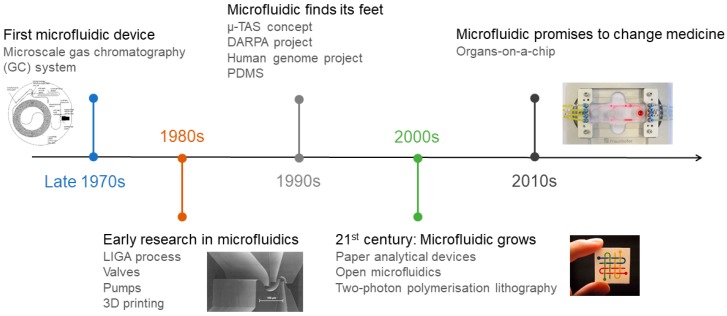
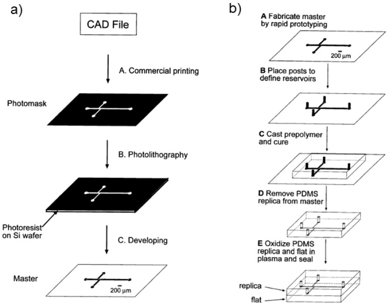
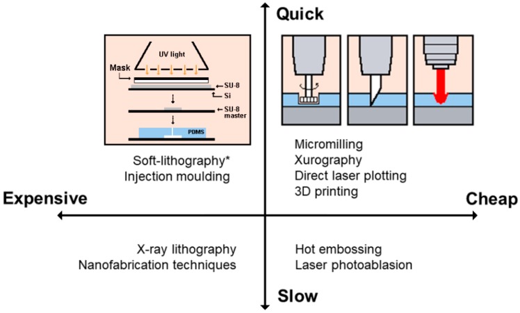
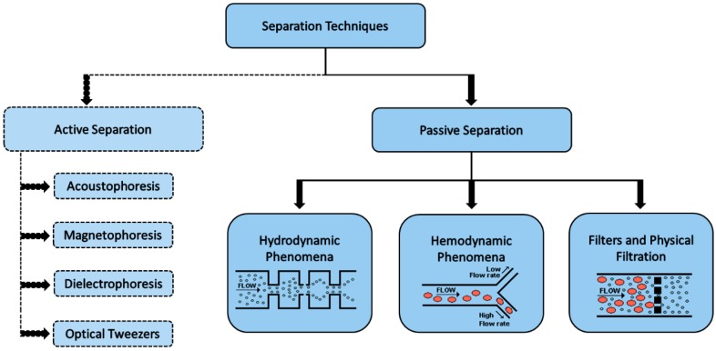
Since the first microfluidic device was developed more than three decades ago, microfluidics is seen as a technology that exhibits unique features to provide a significant change in the way that modern biology is performed. Blood and blood cells are recognized as important biomarkers of many diseases. Taken advantage of microfluidics assets, changes on blood cell physicochemical properties can be used for fast and accurate clinical diagnosis. In this review, an overview of the microfabrication techniques is given, especially for biomedical applications, as well as a synopsis of some design considerations regarding microfluidic devices. The blood cells separation and sorting techniques were also reviewed, highlighting the main achievements and breakthroughs in the last decades.
Keywords: microfabrication; microfluidics; polymers; red blood cells (RBCs); separation and sorting techniques.
Conflict of interest statement
The authors declare no conflicts of interest.
Figures

Similar articles
-
A review of sorting, separation and isolation of cells and microbeads for biomedical applications: microfluidic approaches.Analyst. 2018 Dec 17;144(1):87-113. doi: 10.1039/c8an01061g. Analyst. 2018. PMID: 30402633 Review.
-
A Passive Microfluidic Device Based on Crossflow Filtration for Cell Separation Measurements: A Spectrophotometric Characterization.Biosensors (Basel). 2018 Dec 9;8(4):125. doi: 10.3390/bios8040125. Biosensors (Basel). 2018. PMID: 30544881 Free PMC article.
-
Polymer microfabrication technologies for microfluidic systems.Anal Bioanal Chem. 2008 Jan;390(1):89-111. doi: 10.1007/s00216-007-1692-2. Epub 2007 Nov 8. Anal Bioanal Chem. 2008. PMID: 17989961 Review.
-
Large-Volume Microfluidic Cell Sorting for Biomedical Applications.Annu Rev Biomed Eng. 2015;17:1-34. doi: 10.1146/annurev-bioeng-071114-040818. Epub 2015 Jul 16. Annu Rev Biomed Eng. 2015. PMID: 26194427 Review.
-
Microfluidic technology for cell biology-related applications: a review.J Biol Phys. 2024 Mar;50(1):1-27. doi: 10.1007/s10867-023-09646-y. Epub 2023 Dec 6. J Biol Phys. 2024. PMID: 38055086 Free PMC article. Review.
Cited by
-
Blood Particulate Analogue Fluids: A Review.Materials (Basel). 2021 May 9;14(9):2451. doi: 10.3390/ma14092451. Materials (Basel). 2021. PMID: 34065125 Free PMC article. Review.
-
Point of care sepsis diagnosis: Exploring microfluidic techniques for sample preparation, biomarker isolation, and detection.Biomicrofluidics. 2025 Jul 1;19(4):041502. doi: 10.1063/5.0248096. eCollection 2025 Jul. Biomicrofluidics. 2025. PMID: 40612535 Review.
-
Inertial cell sorting of microparticle-laden flows: An innovative OpenFOAM-based arbitrary Lagrangian-Eulerian numerical approach.Biomicrofluidics. 2021 Feb 19;15(1):014111. doi: 10.1063/5.0035352. eCollection 2021 Jan. Biomicrofluidics. 2021. PMID: 33643513 Free PMC article.
-
Characterization of Nanoparticle Adsorption on Polydimethylsiloxane-Based Microchannels.Sensors (Basel). 2021 Mar 11;21(6):1978. doi: 10.3390/s21061978. Sensors (Basel). 2021. PMID: 33799754 Free PMC article.
-
Features of Vat-Photopolymerized Masters for Microfluidic Device Manufacturing.Bioengineering (Basel). 2024 Jan 15;11(1):80. doi: 10.3390/bioengineering11010080. Bioengineering (Basel). 2024. PMID: 38247957 Free PMC article.
References
-
- Convery N., Gadegaard N. 30 years of microfluidics. Micro Nano Eng. 2019;2:76–91. doi: 10.1016/j.mne.2019.01.003. - DOI
Publication types
LinkOut - more resources
Full Text Sources
Other Literature Sources
