. 2019 Aug 21:26:104386.
doi: 10.1016/j.dib.2019.104386. eCollection 2019 Oct.

Dataset of wind setup in a regulated Venice lagoon

Affiliations

Dataset of wind setup in a regulated Venice lagoon

Riccardo Mel et al. Data Brief. .

Abstract

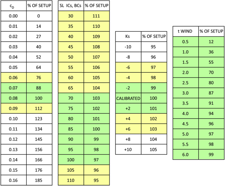
This data article includes the dataset of wind setup in the Venice lagoon computed by means of a 2-D hydrodynamic model. The capability of the model to reproduce the hydrodynamic regime of the lagoon has been extensively investigated, with particular attention to the calibration of the wind shear stress at the water surface, in order to precisely characterize the contribute of wind setup on the water level estimation inside the lagoon. We analyze the wind setup induced considering all the reliable wind speeds (with step of 1 m/s) and wind directions (with step of 30°) potentially blowing over the Venice lagoon, comparing the results obtained considering the present not-regulated configuration of the lagoon (pre-Mo.S.E. scenario) to the regulated configuration (post-Mo.S.E. scenario), which refers to the hydrodynamic regime when the Mo.S.E. movable barriers will be operational. The analysis shows that the wind setup significantly increases when the gates at the three inlets of the Venice lagoon are regulated, up to exceeding four times the pre-Mo.S.E. scenario. We deem this result is of paramount importance for the management of the Mo.S.E. barriers and for the definition of their operating strategy aiming at preventing the flooding at all the urban settlements of the lagoon.

Keywords: Flood hazard; Mo.S.E. barriers; Sea level forecast; Venice lagoon; Wind setup.


Figures

Fig. 1
Fig. 1
Left panel shows the six CPSM lagoonal gauges where we computed the wind setup in both the pre-Mo.S.E. and post-Mo.S.E. scenario for any wind speed and wind direction (see the results in Fig. 2, Fig. 3, Fig. 4). Right panel shows the grid of the hydrodynamic model we used in the present analysis.
Fig. 2
Fig. 2
North – Eastern winds complete analysis: relationship between wind setup and wind speed computed at the six CPSM gauges (Fig. 1). Vertical grey dashed lines represent the maximum wind speed recorded in the period 1999–2018 for that specific direction from which it originates. Left panels represent the pre-Mo.S.E. scenario (panel (a) for wind direction of 0°N, panel (c) for wind direction of 30°N, which has been already presented in the research article , panel (e) for wind direction of 60°N and panel (g) for wind direction of 90°N). Right panels represent the post-Mo.S.E. scenario for the same wind directions (panel (b) for wind direction of 0°N, panel (d) for wind direction of 30°N, which has been already presented in the research article , panel (f) for wind direction of 60°N and panel (h) for wind direction of 90°N).
Fig. 3
Fig. 3
Southern winds complete analysis: relationship between wind setup and wind speed computed at the six CPSM gauges (Fig. 1). Vertical grey dashed lines represent the maximum wind speed recorded in the period 1999–2018 for that specific direction. Left panels represent the pre-Mo.S.E. scenario (panel (a) for wind direction of 120°N, panel (c) for wind direction of 150°N, panel (e) for wind direction of 180°N, which has been already presented in the research article , and panel (g) for wind direction of 210°N). Right panels represent the post-Mo.S.E. scenario for the same wind directions (panel (b) for wind direction of 120°N, panel (d) for wind direction of 150°N, panel (f) for wind direction of 180°N, which has been already presented in the research article , and panel (h) for wind direction of 210°N).
Fig. 4
Fig. 4
North - Western winds complete analysis: relationship between wind setup and wind speed computed at the six CPSM gauges (Fig. 1). Vertical grey dashed lines represent the maximum wind speed recorded in the period 1999–2018 for that specific direction. Left panels represent the pre-Mo.S.E. scenario (panel (a) for wind direction of 240°N, panel (c) for wind direction of 270°N, panel (e) for wind direction of 300°N and panel (g) for wind direction of 330°N). Right panels represent the post-Mo.S.E. scenario for the same wind directions (panel (b) for wind direction of 240°N, panel (d) for wind direction of 270°N, panel (f) for wind direction of 300°N and panel (h) for wind direction of 330°N).
Fig. 5
Fig. 5
The 15 lagoonal gauges where the capability of the model to reproduce wind setup has been calibrated (the 5 gauges represented with red bullets) and tested (all the 15 gauges of the panel) by means of three conventional statistic parameters: the Nash Sutcliffe Model Efficiency (NSE), the Percentage Model Bias (PB) and the Scatter Index (SI).
Fig. 6
Fig. 6
Example of the model capability to reproduce the wind setup: storm surge occurred on February 28th, 2004. Comparison between the SLs computed by the model (blue lines) with those measured (black lines) at three representative stations of Fig. 5, namely: Le Saline in the Northern lagoon, Punta della Salute and Chioggia in the South. Red lines represent the SLs computed by the model neglecting the wind effect.
Fig. 7
Fig. 7
The four performance ranges of the three parameters used in the performance test of the model. Results are shown in Fig. 8, Fig. 9, Fig. 10.
Fig. 8
Fig. 8
Model capability of reproducing the wind setup estimated by the Nash Sutcliffe Model Efficiency (NSE) comparing the computed and measured SLs at the 15 stations represented in Fig. 5. #N/D stands for no data and #N/S for not significant wind setup (less than 5 cm).
Fig. 9
Fig. 9
Model performance estimated by the Percentage Model Bias (PB), comparing the computed and measured SLs at the 15 stations represented in Fig. 5. #N/D stands for no data and #N/S for not significant wind setup (less than 5 cm).
Fig. 10
Fig. 10
Model capability in reproducing the wind setup estimated by the Scatter Index (SI), comparing the computed and measured SLs at the 15 stations represented in Fig. 5. #N/D stands for no data and #N/S for not significant wind setup (less than 5 cm).
Fig. 11
Fig. 11
Sensitivity analysis of the model in computing the wind setup. Panels 1–4 show the percentage of the setup with respect to the values reported in Fig. 2, Fig. 3, Fig. 4. Panel 1 shows the results of the sensitivity analysis for the friction coefficient cd (calibrated value 0.08). Panel 2 shows the results of the sensitivity analysis for the SL imposed at the three inlets (BCs) and the initial uniform water level of the lagoon (ICs). Panel 3 provides the effect on the estimated wind setup induced by variations of the Strickler coefficient with respect to the calibrated set of values. Panel 4 shows the relationship between the duration of the synthetic storm (i.e. constant wind speed and direction) and the percentage of the wind setup with respect to the value reached at equilibrium (i.e. considering a storm duration of 12 hours). As a representative example the results refer to the Chioggia station and to a Bora wind of 18 m/s. However, they do not significantly depend on the station and on wind direction and intensity.

References

    1. Carniello L., Defina A., Fagherazzi S., D'Alpaos L. A combined wind wave-tidal model for the Venice lagoon, Italy. Journal of Geophysical Research – Earth Surface. 2005;110 F04007. October 2005.
    1. Carniello L., D'Alpaos A., Defina A. Modeling wind waves and tidal flows in shallow micro-tidal basins, Estuarine. Coastal and Shelf Science. 2011
    1. D'Alpaos L., Defina A. Mathematical modeling of tidal hydrodynamics in shallow lagoons: a review of open issues and applications to the Venice lagoon. Comput. Geosci. 2006
    1. Defina A. Two-dimensional shallow flow equations for partially dry areas. Water Resour. Res. 2000;36(11):3251–3264.
    1. Mariotti G., Fagherazzi S., Wiberg P., McGlathery K., Carniello L., Defina A. Influence of storm surges and sea level on shallow tidal basin erosive processes. J. Geophys. Res. – Oceans. 2010;115:C11012.

LinkOut - more resources