. 2019 Sep 6;5(9):eaaw2459.
doi: 10.1126/sciadv.aaw2459. eCollection 2019 Sep.

Biomanufacturing of organ-specific tissues with high cellular density and embedded vascular channels

Affiliations

Biomanufacturing of organ-specific tissues with high cellular density and embedded vascular channels

Mark A Skylar-Scott et al. Sci Adv. .

Abstract

Engineering organ-specific tissues for therapeutic applications is a grand challenge, requiring the fabrication and maintenance of densely cellular constructs composed of ~108 cells/ml. Organ building blocks (OBBs) composed of patient-specific-induced pluripotent stem cell-derived organoids offer a pathway to achieving tissues with the requisite cellular density, microarchitecture, and function. However, to date, scant attention has been devoted to their assembly into 3D tissue constructs. Here, we report a biomanufacturing method for assembling hundreds of thousands of these OBBs into living matrices with high cellular density into which perfusable vascular channels are introduced via embedded three-dimensional bioprinting. The OBB matrices exhibit the desired self-healing, viscoplastic behavior required for sacrificial writing into functional tissue (SWIFT). As an exemplar, we created a perfusable cardiac tissue that fuses and beats synchronously over a 7-day period. Our SWIFT biomanufacturing method enables the rapid assembly of perfusable patient- and organ-specific tissues at therapeutic scales.


Figures
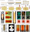
Fig. 1
Fig. 1. Sacrificial writing into functional tissue (SWIFT).
(A) Step-by-step illustration of the SWIFT process. (B) (i) Large-scale microwell culture of approximately (ii) 2.5 ml of EB-based OBBs, compacted to form an (iii) OBB tissue matrix composed of approximately half a billion cells. Scale bar, 300 μm (i). Scale bar, is 200 μm (iii). (C) Time-lapse of sacrificial ink (red) writing via embedded 3D printing within an EB matrix observed from beneath the reservoir. (D) Front view of a vertical line of sacrificial ink printed within an EB matrix. Scale bars, 1 mm (C and D). (E) Examples of the SWIFT process for different OBB-based matrices composed of the following: (i) EBs, (ii) cerebral organoids, and (iii) cardiac spheroids. Row 1: Individual OBBs with characteristic markers. Rows 2 and 3: Cross sections [as indicated in (D) by the dashed line] of immunostained slices and bright-field images, respectively, of the OBB types. Scale bars, 50 μm (top row) and 500 μm (middle and bottom rows). (F) Generation of a helical (vascular) feature in an EB matrix via SWIFT: (i) CAD representation of the system and (ii) corresponding image of sacrificial ink writing within an EB matrix, and (iii) image sequence acquired during embedded 3D printing of a sacrificial ink (left), sacrificial ink evacuation upon incubation (middle), and tissue perfusion using media (dyed blue) through the printed helical vascular channels.
Fig. 2
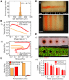
Fig. 2. Living matrix and ink rheology for SWIFT.
(A) Size distribution (n = 413 EBs) of EBs used to form EB matrices. (B) (i) Apparent viscosity as a function of shear rate and (ii) shear storage (closed markers) and loss moduli (open markers) as a function of shear stress of the EB matrix and sacrificial gelatin ink. (C) Temperature effects on the plateau storage moduli (or loss modulus indicated by an asterisk) of the EB matrix and the sacrificial gelatin ink. (D) SWIFT printing of (i) horizontal and (ii) vertical features (vascular templates) embedded at print speeds of 0.5, 1, 2, and 4 mm/s. (E) Effect of print speed on the lumen diameter shown as (i) bright-field and (ii) viability staining images in the context of vertically printed channels and (iii) lumen (channel) diameter as a function of print speed for vascular templates embedded via horizontal and vertical SWIFT printing. Error bars indicate SD (n = 4). Scale bars, 2 mm (D and E). EthD-1, ethidium homodimer-1.
Fig. 3
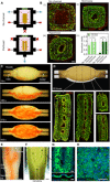
Fig. 3. Perfusable EB tissue fabricated by SWIFT.
(A) Perfusion system used to assess tissue viability following SWIFT printing. (B) Viability staining and analysis following 12 hours of culture of a tissue featuring (i) no channel or perfused with either (ii) normoxic (21% O2) or (iii) with hyperoxygenated (95% O2) media along with the corresponding quantification of the (iv) normalized viability. Scale bars, 500 μm. Error bars indicate SD (n = 4). The dashed lines highlight viability regions that arise from external perfusion. The “core-only” region corresponds to the area located within the innermost line. (C) An image sequence showing the embedded 3D printing of a branched, hierarchical vascular network within a compacted EB-based tissue matrix connected to inlet and outlet tubes, seen entering the tissue from the left and right. Scale bar, 10 mm. (D) Image of the perfusable tissue construct after 12 hours of perfusion (top) and fluorescent image of LIVE/DEAD (green/red) cell viability stains at various sections through the tissue (bottom). The dashed line represents the equivalent viability depth for an avascular control perfused only from the outside, see (Bi). Scale bars, 1 mm (E and F). (E) SWIFT printing of a bifurcating channel for lumen endothelialization. (F) Evacuated channel (highlighted by the white dashed lines) undergoing the perfusion of HUVEC cells. Scale bar, 1 mm. (G and H) Formation of a VECad-positive monolayer of an HUVEC endothelium. Scale bars, 500 μm (G) and 50 μm (H).
Fig. 4
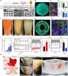
Fig. 4. Perfusable cardiac tissue fabricated by SWIFT.
(A) Cardiac organoid differentiation protocol. (B) Cardiac troponin T and 4′,6-diamidino-2-phenylindole (DAPI) staining in a single cardiac OBB at day 9. Scale bar, 50 μm. (C) Cardiac troponin T, α-actinin, and DAPI staining in a single cardiac OBB at day 9. Scale bar, 10 μm. (D) Cardiac spheroid composition in iPSC-derived cardiac OBB. Cardiomyocytes (CM) are identified as cardiac troponin T-positive (cTnT+) and stromal-like cells (strom.) as cTnT/Vimentin+. (E) Cellular density in compacted cardiac OBB tissue. (F) An image sequence showing the embedding, evacuation, and perfusion of branched vascular channels within a cardiac tissue matrix (tissue dimensions: top width, 6 mm; bottom width, 4.2 mm; depth, 4.2 mm; and height, 12 mm). Scale bars, 2 mm. (G) Viability staining of a SWIFT cardiac tissue (cross section) after 24 hours of perfusion. Scale bar, 500 μm. (H) cTnT, α-actinin, and DAPI staining in a SWIFT cardiac tissue after 8 days of perfusion that shows evidence of sarcomeric remodeling (arrowheads). Scale bar, 10 μm. (I) Vertical displacement of the anchoring flexible prongs due to spontaneous cardiomyocyte contraction showing increasing amplitude over time. On day 8, 2 mM calcium is added to the medium to increase cardiomyocyte contractility (“d8 + Ca”). (J) Comparison of anchor displacement pattern between spontaneous contraction and electrical pacing (1 and 2 Hz) of SWIFT cardiac tissues. (K) Spontaneous contraction pattern before and after administration of 10 μM isoproterenol. (L) Average contraction frequency under isoproterenol treatment. (M) Spontaneous contraction pattern before and after administration of 1 mM 1-heptanol. (N) Maximum peak-to-peak contraction amplitude under 1-heptanol treatment. (O) 3D CAD model of a normal human heart, including a segment of the left anterior descending (LAD) artery and a diagonal branch, downloaded from the National Institutes of Health 3D Print Exchange (additional septal and diagonal branches were added manually, pink). (P) A 1:2 scale polydimethylsiloxane mold is formed using the 3D computed tomography data, and the LAD artery together with diagonal and septal (arrowheads) branches are embedded into a septal-anterior wall wedge [yellow section in (O)] of the cardiac tissue matrix via SWIFT. Scale bar, 5 mm.

References

    1. Miller J. S., The billion cell construct: Will three-dimensional printing get us there? PLOS Biol. 12, e1001882 (2014). - PMC - PubMed
    1. Takebe T., Sekine K., Enomura M., Koike H., Kimura M., Ogaeri T., Zhang R.-R., Ueno Y., Zheng Y.-W., Koike N., Aoyama S., Adachi Y., Taniguchi H., Vascularized and functional human liver from an iPSC-derived organ bud transplant. Nature 499, 481–484 (2013). - PubMed
    1. Zimmermann W.-H., Melnychenko I., Wasmeier G., Didié M., Naito H., Nixdorff U., Hess A., Budinsky L., Brune K., Michaelis B., Dhein S., Schwoerer A., Ehmke H., Eschenhagen T., Engineered heart tissue grafts improve systolic and diastolic function in infarcted rat hearts. Nat. Med. 12, 452–458 (2006). - PubMed
    1. Radisic M., Park H., Shing H., Consi T., Schoen F. J., Langer R., Freed L. E., Vunjak-Novakovic G., Functional assembly of engineered myocardium by electrical stimulation of cardiac myocytes cultured on scaffolds. Proc. Natl. Acad. Sci. U.S.A. 101, 18129–18134 (2004). - PMC - PubMed
    1. Carrier R. L., Papadaki M., Rupnick M., Schoen F. J., Bursac N., Langer R., Freed L. E., Vunjak-Novakovic G., Cardiac tissue engineering: Cell seeding, cultivation parameters, and tissue construct characterization. Biotechnol. Bioeng. 64, 580–589 (1999). - PubMed

Publication types

MeSH terms