Mechanical Follow-the-Leader motion of a hyper-redundant surgical instrument: Proof-of-concept prototype and first tests
- PMID: 31526098
- PMCID: PMC6791023
- DOI: 10.1177/0954411919876466
Mechanical Follow-the-Leader motion of a hyper-redundant surgical instrument: Proof-of-concept prototype and first tests
Abstract
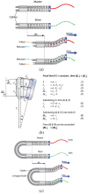
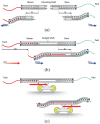
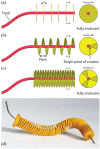
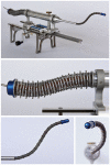
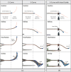
One of the most prominent drivers in the development of surgical procedures is the will to reduce their invasiveness, attested by minimally invasive surgery being the gold standards in many surgical procedures and natural orifices transluminal endoscopic surgery gaining acceptance. A logical next step in this pursuit is the introduction of hyper-redundant instruments that can insert themselves along multi-curved paths referred to as Follow-the-Leader motion. In the current state of the art, two different types of Follow-the-Leader instruments can be distinguished. One type of instrument is robotized; the movements of the shaft are controlled from outside the patient by actuators, for example, electric motors, and a controller storing a virtual track of the desired path. The other type of instrument is more mechanical; the movements of the shaft are controlled from inside the patient by a physical track that guides the shaft along the desired path. While in the robotized approach all degrees of freedom of the shaft require an individual actuator, the mechanical approach makes the number of degrees of freedom independent from the number of actuators. A desirable feature as an increasing number of actuators will inevitably drive up costs and increase the footprint of an instrument. Building the physical track inside the body does, however, impede miniaturization of the shaft's diameter. This article introduces a new fully mechanical approach for Follow-the-Leader motion using a pre-determined physical track that is placed outside the body. This new approach was validated with a prototype called MemoFlex, which supports a Ø5 mm shaft (standard size in minimally invasive surgery) that contains 28-degrees-of-freedom and utilizes a simple steel rod as its physical track. Even though the performance of the MemoFlex leaves room for improvement, especially when following multiple curves, it does validate the proposed concept for Follow-the-Leader motion in three-dimensional space.
Keywords: Follow-the-Leader; hyper-redundant; minimally invasive surgery; natural orifices transluminal endoscopic surgery; pathway surgery; snake-like; surgical instruments; tendon-driven.
Conflict of interest statement
Figures


Similar articles
-
MemoBox: A mechanical follow-the-leader system for minimally invasive surgery.Front Med Technol. 2022 Sep 13;4:938643. doi: 10.3389/fmedt.2022.938643. eCollection 2022. Front Med Technol. 2022. PMID: 36340589 Free PMC article.
-
The MemoFlex II, a non-robotic approach to follow-the-leader motion of a snake-like instrument for surgery using four predetermined physical tracks.Med Eng Phys. 2020 Dec;86:86-95. doi: 10.1016/j.medengphy.2020.10.013. Epub 2020 Oct 28. Med Eng Phys. 2020. PMID: 33261739
-
The Memo Slide: An explorative study into a novel mechanical follow-the-leader mechanism.Proc Inst Mech Eng H. 2017 Dec;231(12):1213-1223. doi: 10.1177/0954411917740388. Epub 2017 Nov 10. Proc Inst Mech Eng H. 2017. PMID: 29125034 Free PMC article.
-
Towards autonomous motion control in minimally invasive robotic surgery.Expert Rev Med Devices. 2016 Aug;13(8):741-8. doi: 10.1080/17434440.2016.1205482. Epub 2016 Jul 11. Expert Rev Med Devices. 2016. PMID: 27376789 Review.
-
Robotic natural orifice transluminal endoscopic surgery (R-NOTES): literature review and prototype system.Minim Invasive Ther Allied Technol. 2015 Feb;24(1):18-23. doi: 10.3109/13645706.2014.992907. Epub 2014 Dec 25. Minim Invasive Ther Allied Technol. 2015. PMID: 25539996 Review.
Cited by
-
Comparison of two cable configurations in 3D printed steerable instruments for minimally invasive surgery.PLoS One. 2022 Oct 4;17(10):e0275535. doi: 10.1371/journal.pone.0275535. eCollection 2022. PLoS One. 2022. PMID: 36194613 Free PMC article. Clinical Trial.
-
MemoBox: A mechanical follow-the-leader system for minimally invasive surgery.Front Med Technol. 2022 Sep 13;4:938643. doi: 10.3389/fmedt.2022.938643. eCollection 2022. Front Med Technol. 2022. PMID: 36340589 Free PMC article.
References
-
- Burgner-Kahrs J, Rucker DC, Choset H. Continuum robots for medical applications: a survey. IEEE T Robot 2015; 31(6): 1261–1280.
-
- Loeve A, Breedveld P, Dankelman J. Scopes too flexible and too stiff. IEEE Pulse 2010; 1(3): 26–41. - PubMed
-
- Chirikjian GS. Theory and applications of hyper-redundant robotic manipulators. PhD Dissertation, California Institute of Technology, Pasadena, CA, 1992.
-
- Choset H, Henning W. A follow-the-leader approach to serpentine robot motion planning. J Aerospace Eng 1999; 12(2): 65–73.
-
- Atallah S, Martin-Perez B, Keller D, et al. Natural-orifice transluminal endoscopic surgery. Brit J Surg 2015; 102(2): e73–e92. - PubMed
MeSH terms
LinkOut - more resources
Full Text Sources

