. 2019 Sep 24;19(19):4126.
doi: 10.3390/s19194126.

A VCO-Based CMOS Readout Circuit for Capacitive MEMS Microphones

Affiliations

A VCO-Based CMOS Readout Circuit for Capacitive MEMS Microphones

Andres Quintero et al. Sensors (Basel). .

Abstract

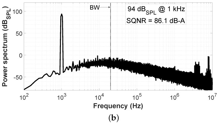
Microelectromechanical systems (MEMS) microphone sensors have significantly improved in the past years, while the readout electronic is mainly implemented using switched-capacitor technology. The development of new battery powered "always-on" applications increasingly requires a low power consumption. In this paper, we show a new readout circuit approach which is based on a mostly digital Sigma Delta ( Σ Δ ) analog-to-digital converter (ADC). The operating principle of the readout circuit consists of coupling the MEMS sensor to an impedance converter that modulates the frequency of a stacked-ring oscillator-a new voltage-controlled oscillator (VCO) circuit featuring a good trade-off between phase noise and power consumption. The frequency coded signal is then sampled and converted into a noise-shaped digital sequence by a time-to-digital converter (TDC). A time-efficient design methodology has been used to optimize the sensitivity of the oscillator combined with the phase noise induced by 1 / f and thermal noise. The circuit has been prototyped in a 130 nm CMOS process and directly bonded to a standard MEMS microphone. The proposed VCO-based analog-to-digital converter (VCO-ADC) has been characterized electrically and acoustically. The peak signal-to-noise and distortion ratio (SNDR) obtained from measurements is 77.9 dB-A and the dynamic range (DR) is 100 dB-A. The current consumption is 750 μ A at 1.8 V and the effective area is 0.12 mm 2 . This new readout circuit may represent an enabling advance for low-cost digital MEMS microphones.

Keywords: MEMS microphone; VCO-ADC; oscillator-based sensor; sigma-delta modulation; time-domain circuit.


Conflict of interest statement

The authors declare no conflict of interest.

Figures

Figure 1
Figure 1
Oscillator-based analog-to-digital converter (ADC) for capacitive Microelectromechanical systems (MEMS) sensors: (a) Sensor connected as the load of an oscillator; (b) sensor connected via an analog interface.
Figure 2
Figure 2
Architecture of the proposed pseudo-differential voltage-controlled oscillator (VCO)-based analog-to-digital converter (VCO-ADC).
Figure 3
Figure 3
Pulse frequency modulation VCO-ADC: (a) Time model; (b) Laplace model; (c) filtered signal w(t); (d) sampled output y[n].
Figure 4
Figure 4
Time-to-digital converter: (a) 31-stage delay line; (b) sampling and demodulation schema.
Figure 5
Figure 5
Chronogram of digital signals in the single-ended channel configuration.
Figure 6
Figure 6
Simulated spectrum for an input signal of 94 dBSPL at 1 kHz: (a) Non-A-Weighted; (b) A-Weighted.
Figure 6
Figure 6
Simulated spectrum for an input signal of 94 dBSPL at 1 kHz: (a) Non-A-Weighted; (b) A-Weighted.
Figure 7
Figure 7
Simulated signal-to-quantization-noise ratio (SQNR) for an input signal of 94 dBSPL at 1 kHz with (a) clock jitter variation and (b) digital delay line mismatch.
Figure 7
Figure 7
Simulated signal-to-quantization-noise ratio (SQNR) for an input signal of 94 dBSPL at 1 kHz with (a) clock jitter variation and (b) digital delay line mismatch.
Figure 8
Figure 8
Single-ended analog core of the proposed VCO-ADC: Impedance converter, 5-stage stacked-RO, and differential cascade voltage switch level shifter.
Figure 9
Figure 9
Simulated analog core dynamic range in the differential configuration for different input levels referred to 94 dBSPL = 12 mVrms (A-Weighting filter applied).
Figure 10
Figure 10
Single-ended digital circuitry of the proposed VCO-ADC: (a) Frequency divider; (b) 31-stage delay line; (c) sampling and demodulation circuit.
Figure 11
Figure 11
Die micrograph and area distribution.
Figure 12
Figure 12
Measured dynamic range for different input levels referred to 94 dBSPL = 12 mVrms (A-Weighting filter applied).
Figure 13
Figure 13
Measured spectrum for an input signal of 94 dBSPL (12 mVrms) at 1 kHz: (a) Non-A-Weighted; (b) A-Weighted.
Figure 14
Figure 14
Measured spectrum for an input signal of 109 dBSPL (67.5 mVrms) at 1 kHz: (a) Non-A-Weighted; (b) A-Weighted.
Figure 15
Figure 15
Measured frequency response (500 Hz to 15 kHz) for an input signal of 94 dBSPL (12 mVrms).
Figure 16
Figure 16
Test fixture used in the acoustical measurements.
Figure 17
Figure 17
Measured spectrum for an acoustic tone of 94 dBSPL at 1 kHz: (a) Non-A-Weighted; (b) A-Weighted.

References

    1. Kim Y., Oh H., Kang S. Proof of Concept of Home IoT Connected Vehicles. Sensors. 2017;17:1289. doi: 10.3390/s17061289. - DOI - PMC - PubMed
    1. Gil D., Ferrández A., Mora-Mora H., Peral J. Internet of things: A review of surveys based on context aware intelligent services. Sensors. 2016;16:1069. doi: 10.3390/s16071069. - DOI - PMC - PubMed
    1. Ghayvat H., Mukhopadhyay S., Gui X., Suryadevara N. WSN-and IOT-based smart homes and their extension to smart buildings. Sensors. 2015;15:10350–10379. doi: 10.3390/s150510350. - DOI - PMC - PubMed
    1. Peña-García N., Aguilera-Cortés L., González-Palacios M., Raskin J.P., Herrera-May A. Design and modeling of a MEMS dual-backplate capacitive microphone with spring-supported diaphragm for mobile device applications. Sensors. 2018;18:3545. doi: 10.3390/s18103545. - DOI - PMC - PubMed
    1. Leinenbach C., van Teeffelen K., Laermer F., Seidel H. A New Capacitive Type MEMS Microphone; Proceedings of the 2010 IEEE 23rd International Conference on Micro Electro Mechanical Systems (MEMS); Hong Kong, China. 24–28 January 2010; pp. 659–662. - DOI