An Impulse Radio PWM-Based Wireless Data Acquisition Sensor Interface
- PMID: 31572068
- PMCID: PMC6767931
- DOI: 10.1109/JSEN.2018.2877889
An Impulse Radio PWM-Based Wireless Data Acquisition Sensor Interface
Abstract
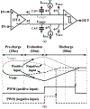
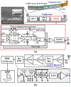
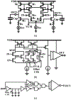
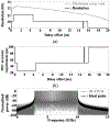
A sensor interface circuit based on impulse radio pulse width modulation (IR-PWM) is presented for low power and high throughput wireless data acquisition systems (wDAQ) with extreme size and power constraints. Two triple-slope analog-to-time converters (ATC) convert two analog signals, each up to 5 MHz in bandwidth, into PWM signals, and an impulse radio (IR) transmitted (Tx) with an all-digital power amplifier (PA) combines them while preserving the timing information by transmitting impulses at the PWM rising and falling edges. On the receiver (Rx) side, an RF-LNA followed by an envelope detector recovers the incoming impulses, and a T-flipflop reverts the impulse sequence back to PWM to be digitized by a time-to-digital converter (TDC). Detailed analysis and design guideline on ATC was introduced, and a proof-of-concept prototype was fabricated for a capacitive micromachined ultrasound transducer (CMUT) imaging system in a 0.18-μm HV CMOS process, occupying 0.18 mm2 active area and consuming 3.94 mW from a 1.8 V supply. The proposed TDC in this prototype yielded 7-bit resolution, while the entire wDAQ achieved 5.8 effective number of bits (ENOB) at 2 × 10 MS/s.
Keywords: Pulse width modulation; impulse radio; wideband communication; wireless data acquisition.
Figures


Similar articles
-
Towards a Reduced-Wire Interface for CMUT-Based Intravascular Ultrasound Imaging Systems.IEEE Trans Biomed Circuits Syst. 2017 Apr;11(2):400-410. doi: 10.1109/TBCAS.2016.2592525. Epub 2016 Sep 20. IEEE Trans Biomed Circuits Syst. 2017. PMID: 27662686 Free PMC article.
-
Toward a reduced-wire readout system for ultrasound imaging.Annu Int Conf IEEE Eng Med Biol Soc. 2014;2014:5080-4. doi: 10.1109/EMBC.2014.6944767. Annu Int Conf IEEE Eng Med Biol Soc. 2014. PMID: 25571135 Free PMC article.
-
A wideband dual-antenna receiver for wireless recording from animals behaving in large arenas.IEEE Trans Biomed Eng. 2013 Jul;60(7):1993-2004. doi: 10.1109/TBME.2013.2247603. Epub 2013 Feb 15. IEEE Trans Biomed Eng. 2013. PMID: 23428612 Free PMC article.
-
A State-of-the-Art Review on CMOS Radio Frequency Power Amplifiers for Wireless Communication Systems.Micromachines (Basel). 2023 Aug 1;14(8):1551. doi: 10.3390/mi14081551. Micromachines (Basel). 2023. PMID: 37630087 Free PMC article. Review.
-
Circuits on miniaturized ultrasound imaging system-on-a-chip: a review.Biomed Eng Lett. 2022 May 12;12(3):219-228. doi: 10.1007/s13534-022-00228-w. eCollection 2022 Aug. Biomed Eng Lett. 2022. PMID: 35892032 Free PMC article. Review.
Cited by
-
Sports Analysis and Action Optimization in Physical Education Teaching Practice Based on Internet of Things Sensor Perception.Comput Intell Neurosci. 2022 Jun 30;2022:7152953. doi: 10.1155/2022/7152953. eCollection 2022. Comput Intell Neurosci. 2022. Retraction in: Comput Intell Neurosci. 2023 Sep 20;2023:9813410. doi: 10.1155/2023/9813410. PMID: 35814534 Free PMC article. Retracted.
-
Intertwined-pulse modulation for compressive data telemetry.Sci Rep. 2022 Jul 13;12(1):11966. doi: 10.1038/s41598-022-16278-0. Sci Rep. 2022. PMID: 35831412 Free PMC article.
References
-
- Murmann B, “ADC performance survey 1997-2015,” [Online]. Available: http://web.stanford.edu/~murmann/adcsurvey.html.
-
- Saijo Y and Van der Steen AFW, “Part 2: The technical potential of IVUS,” in Vascular Ultrasound, Springer, 2003, pp. 51–166.
-
- Garcia-garcia HM, Costa MA, and Serruys PW, “Imaging of coronary atherosclerosis: intravascular ultrasound,” European Heart Journal, pp 2456–2369, Mar. 2010. - PubMed
-
- Liu Q, Chen C, Chang Z, and Pertijs MA, “A mixed-signal multiplexing system for cable-count reduction in ultrasound probes,” IEEE Intl. Ultrasonics Symp, pp. 1–4, Oct. 2015.
Grants and funding
LinkOut - more resources
Full Text Sources
Other Literature Sources
Research Materials
