. 2019 Oct 31;16(159):20190300.
doi: 10.1098/rsif.2019.0300. Epub 2019 Oct 2.

Load-dependent adaptation near zero load in the bacterial flagellar motor

Affiliations

Load-dependent adaptation near zero load in the bacterial flagellar motor

Jasmine A Nirody et al. J R Soc Interface. .

Abstract

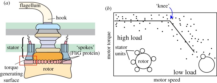
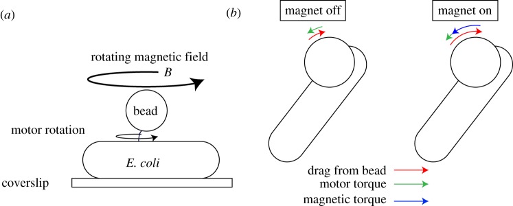
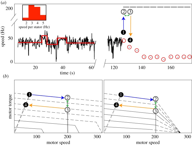
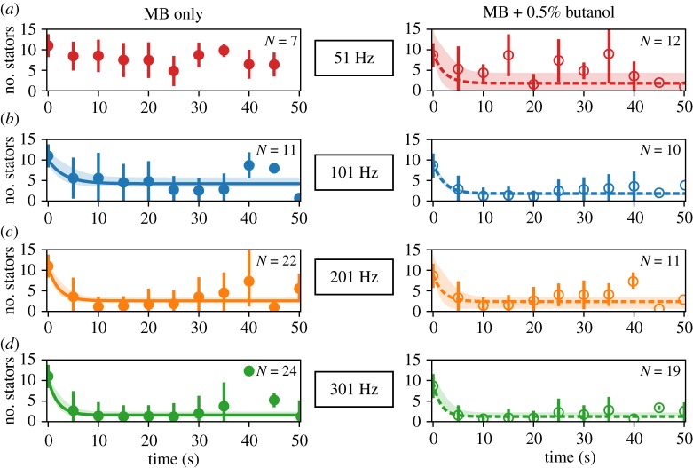
The bacterial flagellar motor is an ion-powered transmembrane protein complex which drives swimming in many bacterial species. The motor consists of a cytoplasmic 'rotor' ring and a number of 'stator' units, which are bound to the cell wall of the bacterium. Recently, it has been shown that the number of functional torque-generating stator units in the motor depends on the external load, and suggested that mechanosensing in the flagellar motor is driven via a 'catch bond' mechanism in the motor's stator units. We present a method that allows us to measure-on a single motor-stator unit dynamics across a large range of external loads, including near the zero-torque limit. By attaching superparamagnetic beads to the flagellar hook, we can control the motor's speed via a rotating magnetic field. We manipulate the motor to four different speed levels in two different ion-motive force (IMF) conditions. This framework allows for a deeper exploration into the mechanism behind load-dependent remodelling by separating out motor properties, such as rotation speed and energy availability in the form of IMF, that affect the motor torque.

Keywords: bacterial flagellar motor; mechanobiology; molecular motors.


Conflict of interest statement

We declare we have no competing interests.

Figures

Figure 1.
Figure 1.
BFM structure and dynamics. (a) The flagellar motor’s rotor consists of a series of large co-axial rings that attach to a flagellar filament via a flexible hook. An active motor can have up to at least 11 torque-generating stator complexes. Stators interact with proteins (FliG) along the rotor’s edge to drive motor rotation. (b) Experiments in recent years have established that the number of torque-generating units varies with external load on the motor (among other possible factors, including IMF). Points in the high-load regime correspond to motors near full occupancy and points at low loads to motors with only one or two. Data shown from [5]. Solid lines are included to guide the eye. (Online version in colour.)
Figure 2.
Figure 2.
Manipulating motor speed using a rotating magnetic field. (a) Experimental set-up: bacteria are immobilized on a coverslip, and a superparamagnetic bead is attached to the motor’s hook; (x, y) positions of the bead are tracked and used to obtain speed versus time traces. Current flowing through a three-pole electromagnet generates a rotating magnetic field B to manipulate the speed of the motor. (b) When the magnet is turned off (left), motor torque (green) must balance viscous drag from the bead (red), resulting in a low rotation speed. When the magnetic field is on and rotating (right), the magnetic torque (blue) takes on most of the drag from the bead, allowing for faster rotation with minimal contribution from motor torque. View is from the top of a counterclockwise-rotating motor. (Online version in colour.)
Figure 3.
Figure 3.
(a) An example experimental trace. Motors are allowed to freely rotate for at least 1 min, during which time a step detection algorithm is used to calculate single stator speeds and determine stator unit stoichiometry (red lines). An inlay shows a histogram of single stator speeds for the plain MB condition. Motors are then rotated at a fixed speed (201 Hz in this example) for 5 s intervals with 0.2 s ‘off’ periods during which the motor speed is recorded. ‘Magnet on’ periods are shown as lines at 201 Hz; red circles depict an example time course of motor remodelling; each red circle contains a single speed calculated within one FFT window. The results of the first ‘magnet on’ period are shown by points 1,2,3,4. At point 1, the motor has seven stator units. When the magnetic field rotates the motor at 201 Hz (blue arrow to point 2), the motor loses two stator units (green arrows) between points 2 and 3 (open circles, unobserved). This loss is observed as a decrease in speed during the first ‘magnet off’ period at point 4. (b) Two possible torque–speed curves for a motor with seven stator units. The left depicts results by Nord et al. [26], which showed that the zero-torque speed of the BFM increased with the number of engaged stator units; the right depicts results by Ryu et al. [11], which suggested that the limiting speed is independent of stator number. Solid lines are based on data; dashed lines are extrapolated as in [11,26]. Dashed grey lines are load lines for the passive beads; solid grey lines show constant speed across stator number during magnet-assisted rotation. Recent experiments by Sato et al. [16] have supported the results of [26] (left). Points 1,2,3,4 depict the same cycle of the magnet from the experimental trace shown in (a). Our assumption that unit binding and unbinding rates are not a function of stator number holds across the torque–speed curves on the right. Considering the left set of curves, this assumption fails when the torque per stator changes drastically at low stator number and high speed—for instance, from two stator units to one (see solid grey line). Further exploration in this regime, likely at finer time resolution than is sampled in this work, will be needed to distinguish between these two scenarios. (Online version in colour.)
Figure 4.
Figure 4.
Motor remodelling following a sudden change in load in plain MB (left) and at low PMF (right). Low PMF environment is attained by mixing 0.5% butanol, shown to act as an ionophore [28], into MB. Time traces show stator unit stoichiometry after magnets are turned on at (a) 51 Hz (red), (b) 101 Hz (blue), (c) 201 Hz (orange) and (d) 301 Hz (green). Circles and error bars show mean ± standard deviation for experimental data in each condition; filled circles represent data collected in plain MB and open circles data collected in low PMF buffer. Lines (solid for MB condition; dashed for low PMF) and shaded regions depict fits of equation (2.3) to data ±3 s.d. We were not able to fit the traces collected at 51 Hz in plain MB (top left, red), which did not lose stators appreciably during magnetic rotation, to this model. (Online version in colour.)
Figure 5.
Figure 5.
Comparison of motor remodelling dynamics at different speeds and IMF levels. (a) A zoomed-in look at the early, most dynamic region from the plots in figure 4; lines shown are fits of equation (2.3) to the data in that figure. As previously, dashed lines represent results in the lowered PMF condition and solid lines in plain MB. The same colour scheme for magnet speed is used throughout this paper. We extrapolate the zero-torque speed in the plain MB condition to vary between 201 and 301 Hz, and between 101 and 201 Hz in the butanol condition; dynamics at these speeds are similar, while those at appreciably higher loads (i.e. 101 Hz in MB, solid blue line) and appreciably lower loads (i.e. 301 Hz in butanol + MB, dashed green line) diverge. (b) Binding rates kon remain relatively constant in both IMF conditions across all four speed levels while (c) unbinding rates koff vary as speed is increased and are on average higher in the lowered IMF condition as compared to in plain MB. Rates kon and koff were calculated from exponential fits to the data of figure 4, except for the points outlined in red (see text for details). These independent effects suggest that the effect of both speed and IMF on stator dynamics in the BFM quite likely works via the relationship of these factors to the load on the motor. Our results also show behaviour consistent with that of a catch bond, as did those of a prior investigation in the higher load regime [18]. (Online version in colour.)

Similar articles

Cited by

References

    1. Berg HC. 2003. The rotary motor of bacterial flagella. Annu. Rev. Biochem. 72, 19–54. (10.1146/annurev.biochem.72.121801.161737) - DOI - PubMed
    1. Nirody JA, Sun Y-R, Lo C-J. 2017. The biophysicist’s guide to the bacterial flagellar motor. Adv. Phys.: X 2, 324–343. (10.1080/23746149.2017.1289120) - DOI
    1. Mandadapu KK, Nirody JA, Berry RM, Oster G. 2015. Mechanics of torque generation in the bacterial flagellar motor. Proc. Natl Acad. Sci. USA 112, E4381–E4389. (10.1073/pnas.1501734112) - DOI - PMC - PubMed
    1. Chang Y, Moon KH, Zhao X, Norris SJ, Motaleb MDA, Liu J. 2019. Structural insights into flagellar stator–rotor interactions. eLife 8, e48979 (10.7554/eLife.48979) - DOI - PMC - PubMed
    1. Chen X, Berg HC. 2000. Torque-speed relationship of the flagellar rotary motor of Escherichia coli. Biophys. J. 78, 1036–1041. (10.1016/S0006-3495(00)76662-8) - DOI - PMC - PubMed

Publication types

MeSH terms

Substances

LinkOut - more resources