An Experimental Slope Method for a More Accurate Measurement of Relative Radiation Doses using Radiographic and Radiochromic Films and Its Application to Megavoltage Small-Field Dosimetry
- PMID: 31576063
- PMCID: PMC6764177
- DOI: 10.4103/jmp.JMP_17_19
An Experimental Slope Method for a More Accurate Measurement of Relative Radiation Doses using Radiographic and Radiochromic Films and Its Application to Megavoltage Small-Field Dosimetry
Abstract
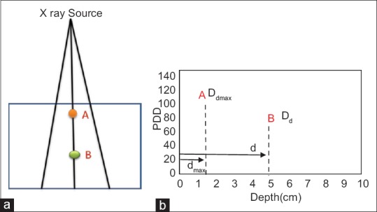
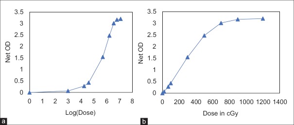
Purpose: An experimental method using the linear portion of the relative film dose-response curve for radiographic and radiochromic films is presented, which can be used to determine the relative depth doses in a variety of very small, medium, and large radiation fields and relative output factors (ROFs) for small fields.
Materials and methods: The film slope (FS) method was successfully applied to obtain the percentage depth doses (PDDs) for external beams of photon and electrons from a Synergy linear accelerator (Elekta AB, Stockholm, Sweden) under reference conditions of 10 cm × 10 cm for photon beam and nominal 10 cm × 10 cm size applicator for electron beam. For small-field dosimetry, the FS method was applied to EDR2 films (Carestream Health, Rochester, NY) for 6 MV photon beam from a linac (Elekta AB, Stockholm, Sweden) and small, circular radiosurgery cones (Elekta AB, Stockholm, Sweden) with diameters of 5, 7.5, 10, 12.5, and 15 mm. The ROFs for all these cones and central axis PDDs for 5, 10, and 15 mm diameter cones were determined at source-to-surface distance of 100 cm. The ROFs for small fields of CyberKnife system were determined using this technique with Gafchromic EBT3 film (Ashland, NJ, USA). The PDDs and ROFs were compared with ion chamber (IC) and Monte Carlo (MC) simulated values.
Results: The maximum percentage deviation of PDDFS with PDDIC for 4, 6, and 15 MV photon beams was within 1.9%, 2.5%, and 1.4%, respectively, up to 20-cm depth. The maximum percentage deviation of PDDFS with PDDIC for electron beams was within 3% for energy range studied of 8-15 MeV. The gamma passing rates of PDDFS with PDDIC were above 96.5% with maximum gamma value of >2, occurring at the zero depths for 4, 6, and 15 MV photons. For electron beams, the gamma passing rates between PDDFS with PDDIC were above 97.7% with a maximum gamma value of 0.9, 1.3, and 0.7 occurring at the zero depth for 8, 12, and 15 MeV. For small field of 5-mm cone, the ROFFS was 0.665 ± 0.021 as compared to 0.674 by MC method. The maximum percentage deviation between PDDFS and PDDMC was 3% for 5 mm and 10 mm and 2% for 15 mm cones with 1D gamma passing rates, respectively, of 95.5%, 96%, and 98%. For CyberKnife system, the ROFFS using EBT3 film and MC published values agrees within 0.2% for for 5 mm cone.
Conclusions: The authors have developed a novel and more accurate method for the relative dosimetry of photon and electron beams. This offers a unique method to determine PDD and ROF with a high spatial resolution in fields of steep dose gradient, especially in small fields.
Keywords: CyberKnife; EBT3 film; EDR2 film; Percentage depth dose; film slope method; relative dosimetry; relative output factor; small-field dosimetry.
Copyright: © 2019 Journal of Medical Physics.
Conflict of interest statement
There are no conflicts of interest.
Figures


Similar articles
-
Application of radiochromic gel dosimetry to commissioning of a megavoltage research linear accelerator for small-field animal irradiation studies.Med Phys. 2021 Mar;48(3):1404-1416. doi: 10.1002/mp.14685. Epub 2021 Feb 6. Med Phys. 2021. PMID: 33378092 Free PMC article.
-
Evaluation of GAFCHROMIC EBT film for Cyberknife dosimetry.Med Phys. 2007 Jun;34(6):1967-74. doi: 10.1118/1.2734384. Med Phys. 2007. PMID: 17654899
-
A novel method for the determination of field output factors and output correction factors for small static fields for six diodes and a microdiamond detector in megavoltage photon beams.Med Phys. 2019 Feb;46(2):944-963. doi: 10.1002/mp.13318. Epub 2018 Dec 24. Med Phys. 2019. PMID: 30521073 Free PMC article.
-
Small-field beam data acquisition, detector dependency, and film-based validation for a novel self-shielded stereotactic radiosurgery system.Med Phys. 2021 Oct;48(10):6121-6136. doi: 10.1002/mp.15091. Epub 2021 Aug 18. Med Phys. 2021. PMID: 34260069
-
Gafchromic EBT3 film dosimetry in electron beams - energy dependence and improved film read-out.J Appl Clin Med Phys. 2016 Jan 8;17(1):360-373. doi: 10.1120/jacmp.v17i1.5970. J Appl Clin Med Phys. 2016. PMID: 26894368 Free PMC article.
References
-
- International Atomic Energy Agency. Absorbed dose Determination in External Beam Radiotherapy: An International Code of Practice for Dosimetry Based on Standards of Absorbed dose to Water. Vienna, Austria: Technical Reports Series; 2000. p. 398.
-
- A protocol for the determination of absorbed dose from high-energy photon and electron beams. Med Phys. 1983;10:741–71. - PubMed
-
- Almond PR, Biggs PJ, Coursey BM, Hanson WF, Huq MS, Nath R, et al. AAPM's TG-51 protocol for clinical reference dosimetry of high-energy photon and electron beams. Med Phys. 1999;26:1847–70. - PubMed
-
- Scott AJ, Nahum AE, Fenwick JD. Using a Monte Carlo model to predict dosimetric properties of small radiotherapy photon fields. Med Phys. 2008;35:4671–84. - PubMed
-
- Palmans H, Andreo P, Huq MS, Seuntjens J, Christaki K. Technical Report Series No 483. Vienna: International Atomic Energy Agency; 2017. [Last accessed on :2019 May 17]. Dosimetry of Small Static Fields used in External Beam Radiotherapy: An IAEA-AAPM International Code of Practice for Reference and Relative dose Determination. Available from: http://www-pub.iaea.org/books/IAEABooks/11075/Dosimetry-of-Small-Static-... .