

Magnetic particle imaging in vascular medicine
- PMID: 31579782
- PMCID: PMC6604583
- DOI: 10.1515/iss-2018-2026
Magnetic particle imaging in vascular medicine
Abstract
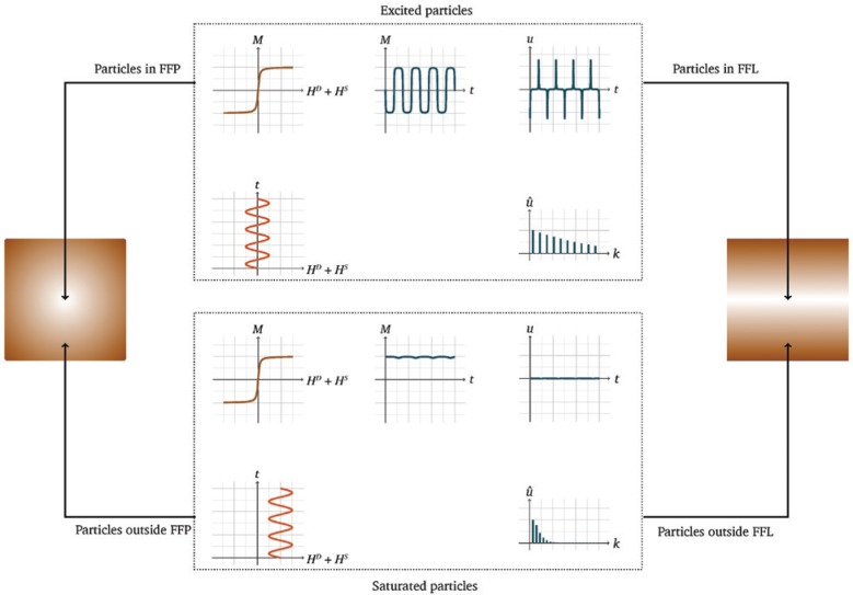
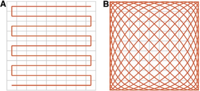
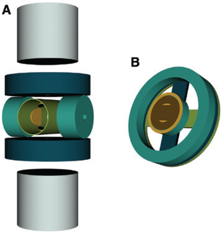
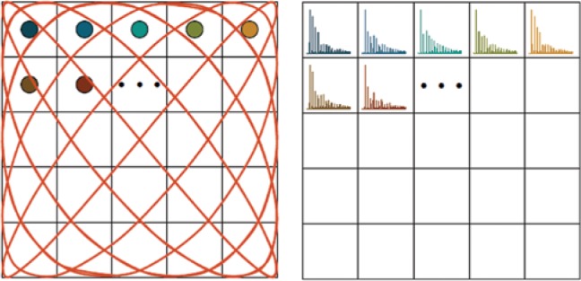
Magnetic particle imaging (MPI) is a new medical imaging technique that enables three-dimensional real-time imaging of a magnetic tracer material. Although it is not yet in clinical use, it is highly promising, especially for vascular and interventional imaging. The advantages of MPI are that no ionizing radiation is necessary, its high sensitivity enables the detection of very small amounts of the tracer material, and its high temporal resolution enables real-time imaging, which makes MPI suitable as an interventional imaging technique. As MPI is a tracer-based imaging technique, functional imaging is possible by attaching specific molecules to the tracer material. In the first part of this article, the basic principle of MPI will be explained and a short overview of the principles of the generation and spatial encoding of the tracer signal will be given. After this, the used tracer materials as well as their behavior in MPI will be introduced. A subsequent presentation of selected scanner topologies will show the current state of research and the limitations researchers are facing on the way from preclinical toward human-sized scanners. Furthermore, it will be briefly shown how to reconstruct an image from the tracer materials' signal. In the last part, a variety of possible future clinical applications will be presented with an emphasis on vascular imaging, such as the use of MPI during cardiovascular interventions by visualizing the instruments. Investigations will be discussed, which show the feasibility to quantify the degree of stenosis and diagnose strokes and traumatic brain injuries as well as cerebral or gastrointestinal bleeding with MPI. As MPI is not only suitable for vascular medicine but also offers a broad range of other possible applications, a selection of those will be briefly presented at the end of the article.
Keywords: MPI scanner; cardiovascular intervention; functional imaging; image reconstruction; magnetic nanoparticles; medical imaging; quantitative imaging; real-time imaging.
©2018 Bakenecker A.C., et al., published by De Gruyter, Berlin/Boston.
Figures
References
-
- Panagiotopoulos N, Duschka RL, Ahlborg M, Bringout G, Debbeler C, Graeser M, et al. Magnetic particle imaging: current developments and future directions. Int J Nanomed 2015;10:3097–114. - PMC - PubMed
- Panagiotopoulos N, Duschka RL, Ahlborg M, Bringout G, Debbeler C, Graeser M. et al. Magnetic particle imaging: current developments and future directions. Int J Nanomed. 2015;10:3097–114. - PMC - PubMed
-
- Knopp T, Buzug TM. Magnetic Particle Imaging: an Introduction to Imaging Principles and Scanner Instrumentation. Berlin: Springer; 2012. DOI: 10.1007/978-3-642-04199-0.
- Knopp T, Buzug TM. Magnetic Particle Imaging: an Introduction to Imaging Principles and Scanner Instrumentation. Berlin: Springer; 2012. - DOI
-
- Weizenecker J, Gleich B, Borgert J. Magnetic particle imaging using a field free line. J Phys D Appl Phys 2008;41:105009.
- Weizenecker J, Gleich B, Borgert J. Magnetic particle imaging using a field free line. J Phys D Appl Phys. 2008;41:105009.
-
- Erbe M, Knopp T, Sattel TF, Biederer S, Buzug TM. Experimental generation of an arbitrary rotated field-free line for use in magnetic particle imaging. Med Phys 2011;38:5200–7. - PubMed
- Erbe M, Knopp T, Sattel TF, Biederer S, Buzug TM. Experimental generation of an arbitrary rotated field-free line for use in magnetic particle imaging. Med Phys. 2011;38:5200–7. - PubMed
Publication types
LinkOut - more resources
Full Text Sources
Research Materials