. 2019 Oct 4;10(1):4539.
doi: 10.1038/s41467-019-12583-x.

Visible and infrared three-wavelength modulated multi-directional actuators

Affiliations

Visible and infrared three-wavelength modulated multi-directional actuators

Bo Zuo et al. Nat Commun. .

Abstract

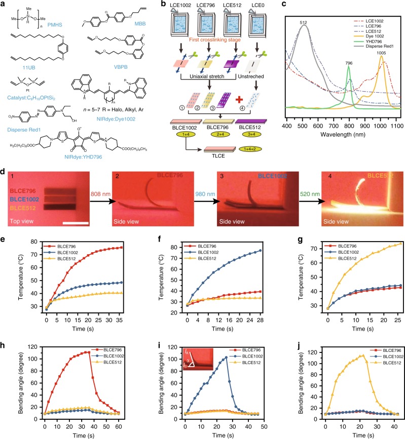
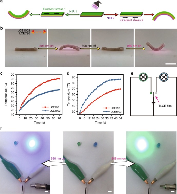
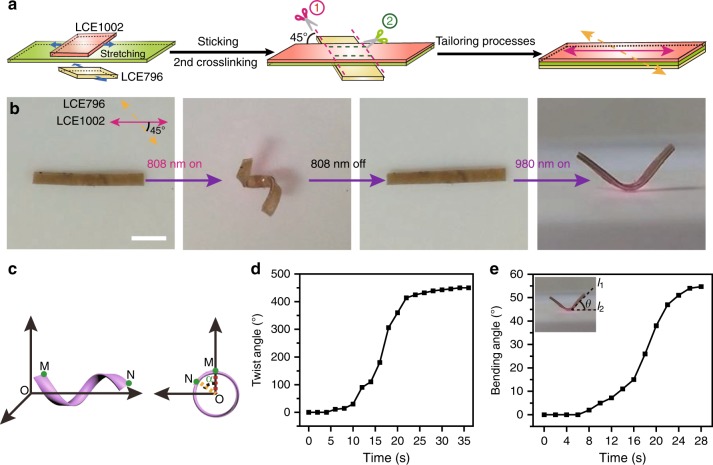
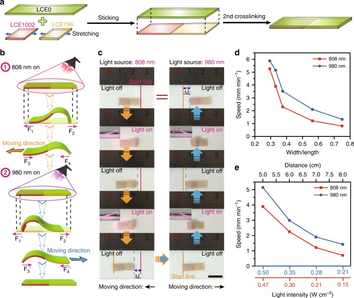
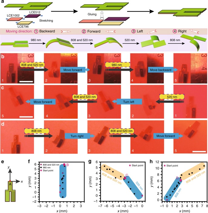
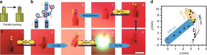
In recent years, light-guided robotic soft actuators have attracted intense scientific attention and rapidly developed, although it still remains challenging to precisely and reversibly modulate the moving directions and shape morphing modes of soft actuators with ease of stimulating operation. Here we report a strategy of building a multi-stimuli-responsive liquid crystal elastomer soft actuator system capable of performing not only multi-directional movement, but also different shape morphing modes. This strategy is based on the selective stimulation of specific domains of the hierarchical structured actuator through the modulation of three wavelength bands (520, 808, 980 nm) of light stimulus, which release the actuation system from light scanning position/direction restriction. Three near-infrared dual-wavelength modulated actuators and one visible/infrared tri-wavelength modulated multi-directional walker robot are demonstrated in this work. These devices have broad application prospects in robotic and biomimetic technology.


Conflict of interest statement

The authors declare no competing interests.

Figures

Fig. 1
Fig. 1
Design and investigation of NIR wavelength-selective responsive properties of LCE system. a The chemical components used in this LCE system. b Schematic illustration of the preparation procedures of BLCE1002, BLCE796, BLCE512 and TLCE. c UV-Vis-IR absorption spectra of YHD796 (conc. = 1.4 × 10−3 mg mL−1), Dye1002 (conc = 1.5 × 10−3 mg mL−1) and Disperse Red1 (conc = 5.0 × 10−3 mg mL−1) in dichloromethane, and the corresponding LCE796, LCE1002, and LCE512 films. d The photographs of the actuation motions of BLCE796, BLCE1002, and BLCE512 films with one end fixed, under the stimulation of 808 nm, 980 nm, and 520 nm light respectively (scale bar = 0.5 cm). Temperature profiles of BLCE796, BLCE1002, and BLCE512 films irradiated by (e) 808 nm, (f) 980 nm, and (g) 520 nm light. The diagrams of the included angle α of BLCE796, BLCE1002, and BLCE512 plotted against the illumination time of (h) 808 nm, (i) 980 nm, and (j) 520 nm light. Source data are provided as a Source Data file
Fig. 2
Fig. 2
NIR dual-wavelength modulated two-way switch. a Schematic illustration and b the real image records of NIR dual-wavelength-selective shape deformations of a TLCE film (scale bar = 0.5 cm). The diagrams of the surface temperatures of the bottom LCE796 and upper LCE1002 layers of the TLCE sample plotted against the illumination time of c 808 nm and d 980 nm NIR light. e Circuit diagram of the designed two-way switch device. f Photographs of a TLCE film coated with conductive material acting as a two-way switch under the control of 808 nm and 980 nm NIR light. Source data are provided as a Source Data file
Fig. 3
Fig. 3
NIR dual-wavelength modulated dual-motion-mode shape morpher. a Schematic illustration of the preparation procedures of TLCE with a crossed angle of 45° between the alignment directions of the bottom LCE796 layer and top LCE1002 film. b The photographs of the actuating motions of TLCE under the illumination of 808 nm and 980 nm NIR light respectively (scale bar = 0.5 cm). c Schematic definition of the twist angle α. Twist angle α and included angle θ of TLCE plotted against the illumination time of d 808 nm and e 980 nm NIR light, respectively. Source data are provided as a Source Data file
Fig. 4
Fig. 4
NIR dual-wavelength modulated two-way inchworm-like walker. a Schematic illustration of the fabrication of a two-way inchworm-like bilayered LCE walker. b Diagrammatic drawing of the force analysis for inchworm-like walker under the on-off stimulation of 808 nm and 980 nm NIR light. c Photographs showing the two-way inchworm-like walker moving left and right upon on-off irradiation of 808 nm and 980 nm NIR light (scale bar = 1.0 cm). The speed diagrams of the inchworm-like walker plotted against d varied width/length ratios (length = 16 mm) and e varied light intensities (length = 16 mm, W/L ratio = 0.33). Source data are provided as a Source Data file
Fig. 5
Fig. 5
Photo-modulated multi-directional bilayered LCE walker. a Schematic illustration of the fabrication protocol and the moving mechanism of a multi-directional bilayered LCE walker. Photographs showing the multi-directional walker (b) moving either forward or backward upon on-off irradiation of 808/520 nm or 980 nm light, c moving left and then forward upon on-off irradiation of 520 nm and then 808/520 nm light, d moving right and then forward upon on-off irradiation of 808 nm and then 808/520 nm light. e The definition of the starting position coordinate of the LCE walker in x–y plane. The real-time position coordinate of the midpoint A of the LCE walker recorded in f moving forward and backward manner, g moving left and then forward manner, h moving right and then forward manner. Scale bar = 1.0 cm. Source data are provided as a Source Data file
Fig. 6
Fig. 6
Photo-guided parallel parking of LCE walker robot. Schematic illustration of a the parallel parking of a vehicle and b how a vehicle accomplishes such a horizontal movement. c Photographs showing the process of such a vehicle-like walker robot moving horizontally from position A to position D under the stimulation of 808 nm, 520 nm, and 980 nm light (scale bar = 1.0 cm). d The real-time position coordinate of the midpoint A of this LCE walker recorded in parallel parking manner. Source data are provided as a Source Data file

References

    1. Kim S, Laschi C, Trimmer B. Soft robotics: a bioinspired evolution in robotics. Trends Biotechnol. 2013;31:287–294. doi: 10.1016/j.tibtech.2013.03.002. - DOI - PubMed
    1. Rus D, Tolley MT. Design, fabrication and control of soft robots. Nature. 2015;521:467–475. doi: 10.1038/nature14543. - DOI - PubMed
    1. Dickey MD. Stretchable and soft electronics using liquid metals. Adv. Mater. 2017;29:1606425. doi: 10.1002/adma.201606425. - DOI - PubMed
    1. Liu YH, Pharr M, Salvatore GA. Lab-on-skin: a review of flexible and stretchable electronics for wearable health monitoring. ACS Nano. 2017;11:9614–9635. doi: 10.1021/acsnano.7b04898. - DOI - PubMed
    1. Bauer S, et al. 25th anniversary article: a soft future: from robots and sensor skin to energy harvesters. Adv. Mater. 2014;26:149–162. doi: 10.1002/adma.201303349. - DOI - PMC - PubMed

Publication types