. 2019 Jun 27;10(33):7755-7761.
doi: 10.1039/c9sc02576f. eCollection 2019 Sep 7.

Uncovering two kinetic factors in the controlled growth of topologically distinct core-shell metal-organic frameworks

Affiliations

Uncovering two kinetic factors in the controlled growth of topologically distinct core-shell metal-organic frameworks

Fang Wang et al. Chem Sci. .

Abstract

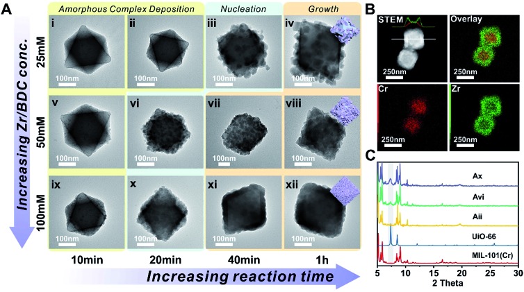
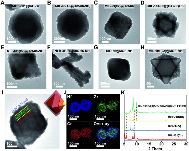
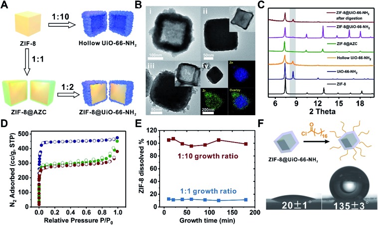
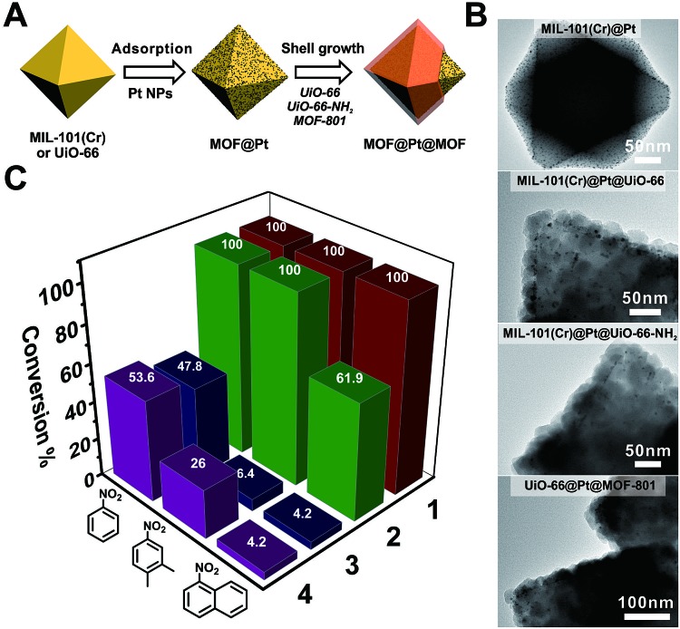
Constructing core-shell metal-organic frameworks (MOFs) based on two topologically distinct MOFs is a great way to increase MOF material complexity and explore their new functions. However, such a nucleation process is energetically less favored compared to epitaxial growth due to mismatched unit cell parameters. Here, two kinetic factors, nucleation kinetics and dissolution kinetics, are revealed to be two key factors in overcoming this challenge. Through kinetic control, we demonstrate the growth of 4 types of Zr/Hf-MOF shells uniformly and contiguously on 7 different core MOFs including ZIF-8, an acid labile core. Taking advantage of the modular synthesis of Zr-MOFs, we demonstrate that post-synthetic covalent surface modification on a non-functionalizable MOF surface can be made possible through core-shell construction. We also demonstrated that the size selective catalytic behavior can be systematically tuned through changing either the ligand length or ligand functionality.


Figures

Fig. 1
Fig. 1. (A) TEM images of MIL-101(Cr)@UiO-66 at different growth stages; (B) STEM and EDS elemental mapping images of MIL-101(Cr)@UiO-66 (Axii); (C) PXRD patterns of MIL-101(Cr) (red, simulated), UiO-66 (blue, simulated), and MIL-101(Cr)@UiO-66 (Aii, yellow; Avi, green; Ax, purple). The grey zone highlights the characteristic diffraction peak of the (111) facet of UiO-66.
Fig. 2
Fig. 2. TEM images of (A) MOF-801@UiO-66, (B) MIL-96(Al)@UiO-66-NH2, (C) MIL-53(Cr)@UiO-66, (D) MIL-101(Cr)@UiO-66(Hf), (E) MIL-101(Cr)@UiO-66-NH2, (F) Ni-MOF-74@UiO-66-NH2, (G) UiO-66@MOF-801, (H) MIL-101(Cr)@MOF-801 and (I) MIL-101(Cr)@UiO-66(Zr)@MOF-801(Hf); (J) EDS elemental mapping images of MIL-101(Cr)@UiO-66(Zr)@MOF-801(Hf); (K) PXRD patterns of MIL-101(Cr) (red, simulated), UiO-66(Zr) (blue, simulated), MOF-801(Hf) (yellow, simulated) and MIL-101(Cr)@UiO-66(Zr)@MOF-801(Hf) (green).
Fig. 3
Fig. 3. (A) Schematic illustration of the growth process of UiO-66-NH2 on ZIF-8. (B) TEM images of hollow UiO-66-NH2 (i), ZIF-8@AZC (ii), and ZIF-8@UiO-66-NH2 (iii), and EDS elemental mapping images of ZIF-8@AZC (iv). The insets in ii and iii are the TEM images of the core–shell particles after acid digestion. (C) PXRD patterns of ZIF-8 (black, simulated), UiO-66-NH2 (blue, simulated), hollow UiO-66-NH2 (yellow), ZIF-8@AZC (green), ZIF-8@UiO-66-NH2 (purple), and ZIF-8@UiO-66-NH2 after acid digestion (red). (D) N2 adsorption–desorption isotherms (77 K) of ZIF-8 (blue), ZIF-8@UiO-66-NH2 (green), and UiO-66-NH2 (red). (E) The dissolution kinetics of ZIF-8 from ZIF-8@UiO-66-NH2 during the shell growth process. (F) Water contact angle measurements for non-functionalized ZIF-8@UiO-66-NH2 (left) and alkane modified ZIF-8@UiO-66-NH2 (right).
Fig. 4
Fig. 4. (A) Schematic illustration of the fabrication process of Pt NP-containing core–shell MOF catalysts. (B) TEM images of MIL-101(Cr)@Pt, MIL-101(Cr)@Pt@UiO-66, MIL-101(Cr)@Pt@UiO-66-NH2, and UiO-66@Pt@MOF-801. (C) The conversion of nitrobenzene, 2,3-dimethyl nitrobenzene, and 1-nitronaphthalene over different catalysts after 150 min of the hydrogenation reaction. For clear visualization of Pt NPs, core–shell particles with very thin shell layers were selected for imaging. More representative images can be found in Fig. S22–S24.

References

    1. Gawande M. B., Goswami A., Asefa T., Guo H., Biradar A. V., Peng D. L., Zboril R., Varma R. S. Chem. Soc. Rev. 2015;44:7540–7590. - PubMed
    1. Li J. F., Zhang Y. J., Ding S. Y., Panneerselvam R., Tian Z. Q. Chem. Rev. 2017;117:5002–5069. - PubMed
    1. Ghosh Chaudhuri R., Paria S. Chem. Rev. 2012;112:2373–2433. - PubMed
    1. Khaletskaya K., Reboul J., Meilikhov M., Nakahama M., Diring S., Tsujimoto M., Isoda S., Kim F., Kamei K.-i., Fischer R. A., Kitagawa S., Furukawa S. J. Am. Chem. Soc. 2013;135:10998–11005. - PubMed
    1. Feng E., Zheng T., He X., Chen J., Tian Y. Sci. Adv. 2018;4:3494. - PMC - PubMed