Finite element study of controlling factors of anterior intrusion and torque during Temporary Skeletal Anchorage Device (TSAD) dependent en masse retraction without posterior appliances: Biocreative hybrid retractor (CH-retractor)
- PMID: 31589469
- PMCID: PMC8051234
- DOI: 10.2319/050619-315.1
Finite element study of controlling factors of anterior intrusion and torque during Temporary Skeletal Anchorage Device (TSAD) dependent en masse retraction without posterior appliances: Biocreative hybrid retractor (CH-retractor)
Abstract
Objectives: To evaluate, using the finite element method (FEM), the factors that allow control of the anterior teeth during en masse retraction with the Biocreative hybrid retractor (CH-retractor) using different sizes of nickel-titanium (NiTi) archwires and various gable bends on the stainless-steel (SS) archwires.
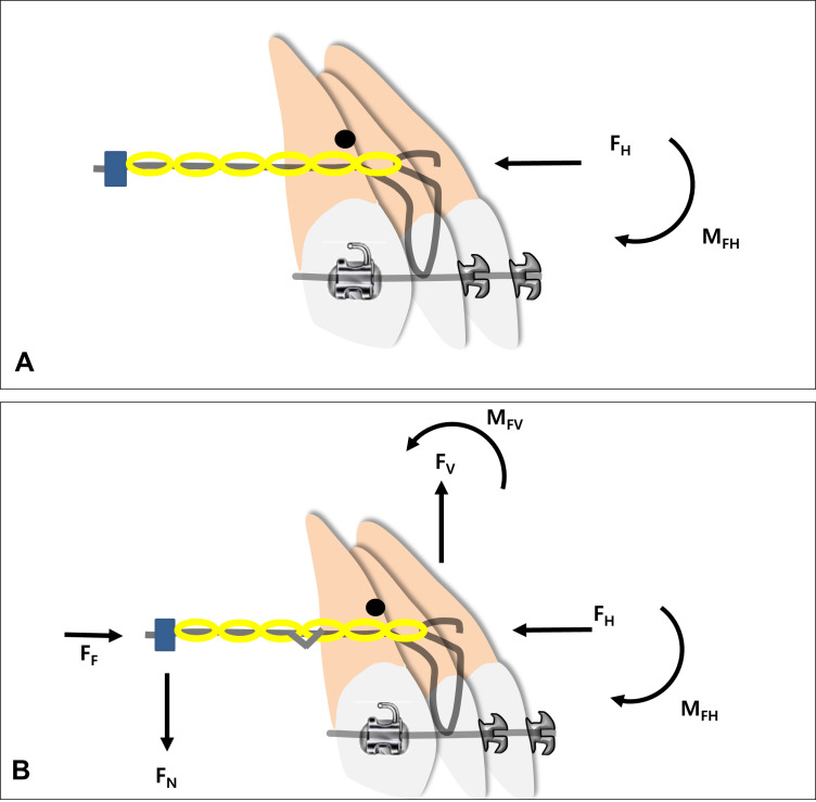
Materials and methods: Using FEM, the anterior archwire section, engaged on the anterior dentition, was modeled in NiTi, and another assembly, the posterior guiding archwire, was modeled in SS. Two dimensions (0.016 × 0.022- and 0.017 × 0.025-inch NiTi) of the anterior archwires and different degrees (0°, 15°, 30°, 45°, and 60°) of the gable bends on the guiding wire were applied to the CH-retractor on the anterior segment to evaluate torque and intrusion with 100-g retraction force to TSADs. Finite element analysis permitted sophisticated analysis of anterior tooth displacement.
Results: With a 0° gable bend all anterior teeth experienced extrusion. The canines showed a larger amount of extrusion than did the central and lateral incisors. With a gable bend of >15°, all anterior teeth exhibited intrusion. Bodily movement of the central incisor required a 30°∼45° gable bend when using anterior segments of 0.016 × 0.022-inch NiTi and 15°∼30° gable bend with the 0.017 × 0.025-inch NiTi.
Conclusions: With the CH-retractor, varying the size of the NiTi archwire and/or varying the amount of gable bend on the SS archwire affects control of the anterior teeth during en masse retraction without a posterior appliance.
Keywords: Biocreative orthodontic strategy; En masse retraction; FEA; Gable bend; NiTi; TSAD; Torque.
Figures


References
-
- Chung KR, Cho JH, Kim SH, Kook YA, Cozzani M. Unusual extraction treatment in Class II division 1 using C-orthodontic mini-implants. Angle Orthod. 2007;77:155–166. - PubMed
-
- Chung KR, Choo H, Lee JH, Kim SH. Atypical orthodontic extraction pattern managed by differential en-masse retraction against a temporary skeletal anchorage device in the treatment of bimaxillary protrusion. Am J Orthod Dentofacial Orthop. 2011;140:423–432. - PubMed
-
- Chung KR, Nelson G, Kim SH, Kook YA. Severe bidentoalveolar protrusion treated with orthodontic microimplant-dependent enmasse retraction. Am J Orthod Dentofacial Orthop. 2007;132:105–115. - PubMed
-
- Chung KR, Kim SH, Kook YA, Sohn JH. Anterior torque control using partial-osseointegrated mini-implants: Biocreative therapy type I technique. World J Orthod. 2008;9:95–104. - PubMed
-
- Kim SH, Chung KR, Nelson G. The Biocreative strategy: part 1 foundations. J Clin Orthod. 2018;52:258–274. - PubMed
MeSH terms
LinkOut - more resources
Full Text Sources
Research Materials