

Application of the foramina of the trigeminal nerve as landmarks for analysis of craniofacial morphology
- PMID: 31598489
- PMCID: PMC6769262
- DOI: 10.4041/kjod.2019.49.5.326
Application of the foramina of the trigeminal nerve as landmarks for analysis of craniofacial morphology
Abstract
Objective: The objective of this study was to develop new parameters based on the foramina of the trigeminal nerve and to compare them with the conventional cephalometric parameters in different facial skeletal types.
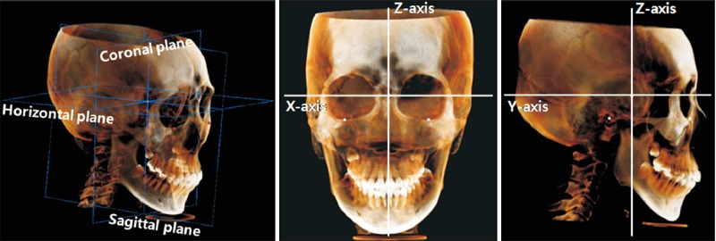
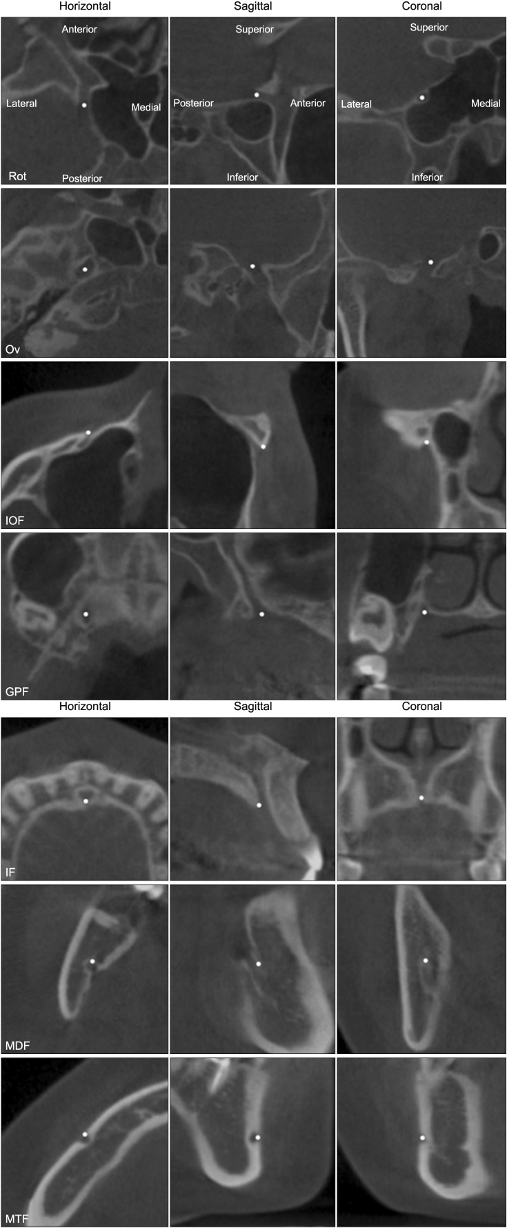
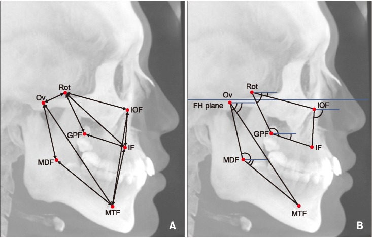
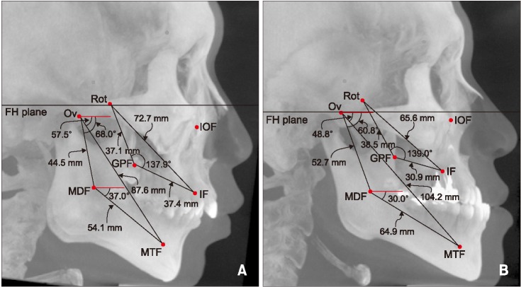
Methods: Cone-beam computed tomography (CBCT) scans and cephalograms from 147 adult patients (57 males and 90 females; mean age, 26.1 years) were categorized as Class I (1° < ANB < 3°), Class II (ANB > 5°), and Class III (ANB < -1°). Seven foramina in the craniofacial area-foramen rotundum (Rot), foramen ovale (Ov), infraorbital foramen, greater palatine foramen, incisive foramen (IF), mandibular foramen (MDF), and mental foramen (MTF)-were identified in the CBCT images. Various linear, angular, and ratio parameters were compared between the groups by using the foramina, and the relationship between the new parameters and the conventional cephalometric parameters was assessed.
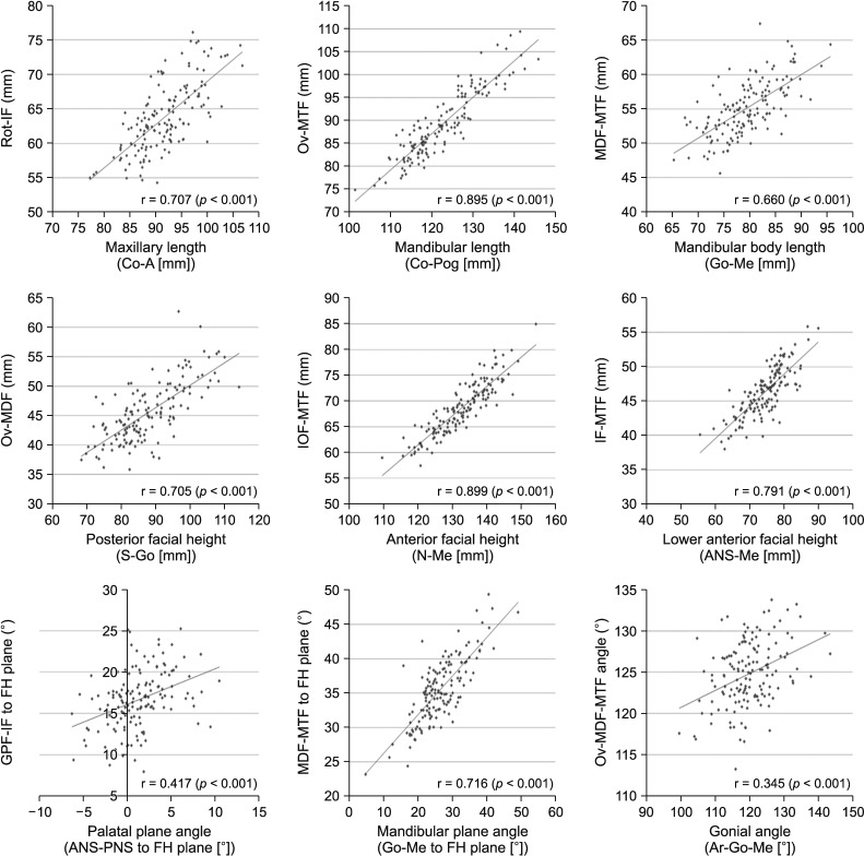
Results: The distances between the foramina in the cranial base did not differ among the three groups. However, the Rot-IF length was shorter in female Class III patients, while the Ov-MTF length, MDF-MTF length, and Ov-MDF length were shorter in Class II patients than in Class III patients of both sexes. The MDF-MTF/FH plane angle was larger in Class II patients than in Class III patients of both sexes. Most parameters showed moderate to high correlations, but the Ov-MDF-MTF angle showed a relatively low correlation with the gonial angle.
Conclusions: The foramina of the trigeminal nerve can be used to supplement assessments based on the conventional skeletal landmarks on CBCT images.
Keywords: Anatomy; Computed tomography; Foramen; Trigeminal nerve.
© 2019 The Korean Association of Orthodontists.
Conflict of interest statement
CONFLICTS OF INTEREST: No potential conflict of interest relevant to this article was reported.
Figures
References
-
- Downs WB. The role of cephalometrics in orthodontic case analysis and diagnosis. Am J Orthod. 1952;38:162–182.
-
- Ricketts RM. Cephalometric synthesis: an exercise in stating objectives and planning treatment with tracings of the head roentgenogram. Am J Orthod. 1960;46:647–673.
-
- Ricketts RM. A foundation for cephalometric communication. Am J Orthod. 1960;46:330–357.
-
- Steiner CC. Cephalometrics for you and me. Am J Orthod. 1953;39:729–755.
-
- Steiner CC. Cephalometrics in clinical practice. Angle Orthod. 1959;29:8–29.
LinkOut - more resources
Full Text Sources
Miscellaneous