. 2019 Oct 29;116(44):22366-22375.
doi: 10.1073/pnas.1905994116. Epub 2019 Oct 14.

Fundamental helical geometry consolidates the plant photosynthetic membrane

Affiliations

Fundamental helical geometry consolidates the plant photosynthetic membrane

Yuval Bussi et al. Proc Natl Acad Sci U S A. .

Abstract

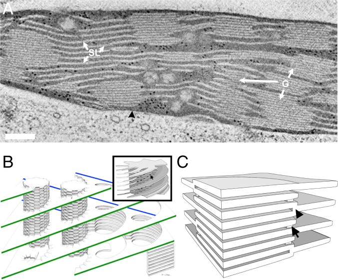
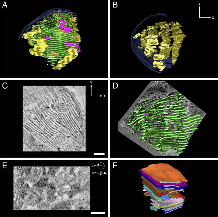
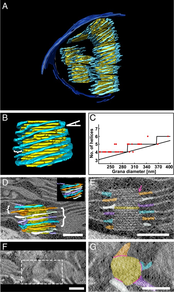
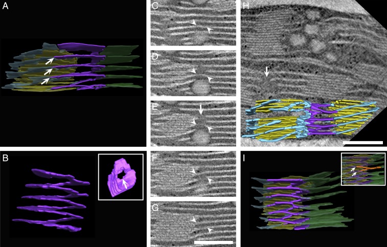
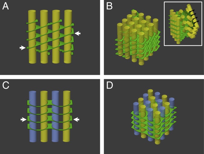
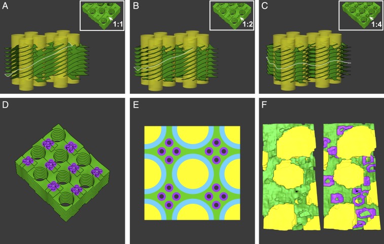
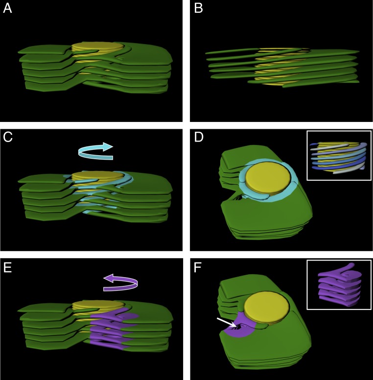
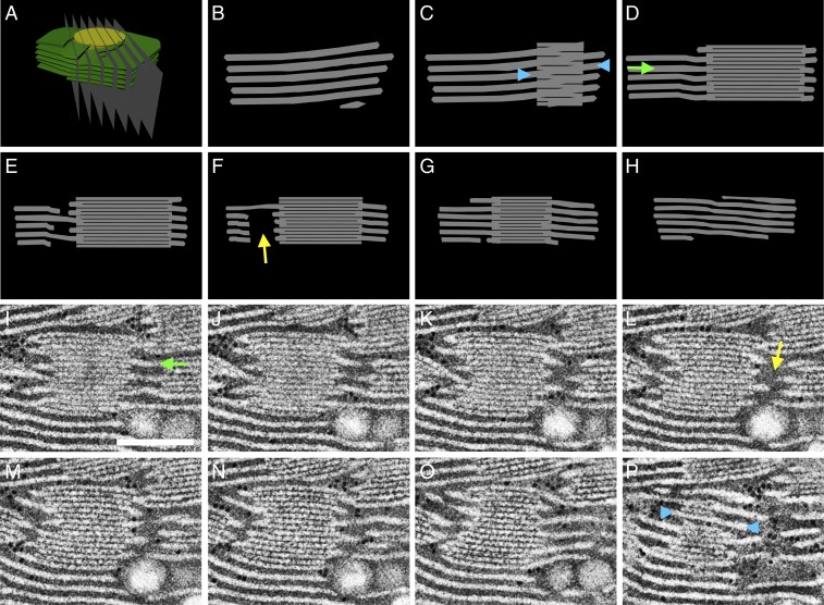
Plant photosynthetic (thylakoid) membranes are organized into complex networks that are differentiated into 2 distinct morphological and functional domains called grana and stroma lamellae. How the 2 domains join to form a continuous lamellar system has been the subject of numerous studies since the mid-1950s. Using different electron tomography techniques, we found that the grana and stroma lamellae are connected by an array of pitch-balanced right- and left-handed helical membrane surfaces of different radii and pitch. Consistent with theoretical predictions, this arrangement is shown to minimize the surface and bending energies of the membranes. Related configurations were proposed to be present in the rough endoplasmic reticulum and in dense nuclear matter phases theorized to exist in neutron star crusts, where the right- and left-handed helical elements differ only in their handedness. Pitch-balanced helical elements of alternating handedness may thus constitute a fundamental geometry for the efficient packing of connected layers or sheets.

Keywords: electron tomography; helical membrane structures; membrane elasticity; minimal surfaces; thylakoid membranes.


Conflict of interest statement

The authors declare no competing interest.

Figures

Fig. 1.
Fig. 1.
Models of the plant thylakoid membrane. (A) A 10-nm-thick STEM tomographic slice of lettuce chloroplast. The grana stacks (G) are interconnected by unstacked stroma thylakoids (SL). Both membrane domains are immersed in an aqueous matrix, called stroma, which in turn is bordered by the chloroplast envelope (black arrowhead). (Scale bar, 200 nm.) (B) The helical model. The stroma lamellae wrap around the grana as right-handed helices, connecting to the thylakoids within the stack through slit-like apertures located at the rim of the stacks. A single file of grana is shown, with its oppositely sloped long edges marked in green and blue. Reprinted with permission from ref. . (Inset) A model of a granum–stroma assembly, configured akin to the helical model, composed of a granum core surrounded by multiple helical frets. The arrow marks a slit at the edge of the granum. Adapted by permission from ref. , Springer Nature: Plant Molecular Biology, copyright 2011. (C) The bifurcation model. The grana stacks are formed by bifurcations of the stroma lamellae (black arrowhead). Neighboring discs in the stacks are additionally connected by internal membrane bridges located near the bifurcation sites at the grana periphery (arrow).
Fig. 2.
Fig. 2.
Overall network architecture and domain organization. (A) A 3D model of a dark-adapted lettuce thylakoid network generated by segmentation of a tomographic reconstruction by TEM. The grana and stroma thylakoids are colored yellow and green, respectively; the chloroplast envelope is shown in blue and the magenta-colored inclusions associated with the thylakoids are plastoglobules. (C and D) Tomographic slices ∼10 nm thick presented approximately perpendicular (C) and parallel (D) to the plane of the grana thylakoids. The 4 horizontal segments apparent in D correspond to the 4 serial sections that constitute the tomogram. Models showing (B) only grana stacks, to enable visualization of grana piling into columns, (E) only stroma lamellae (superimposed on a ∼10-nm-thick tomographic slice), to enable visualization of the sheets, cross-overs, and bifurcations, and (F) a group of stroma lamellar sheets with each individual sheet displayed in a different color, depicting the parallel organization of the sheets. (Scale bars, 250 nm.)
Fig. 3.
Fig. 3.
Grana are surrounded by multiple right-handed helices. (A, B, and D) A 3D model generated from segmentation of TEM (A) and STEM (B and D) tomographic data consisting of single and multiple grana (yellow) each surrounded by multiple stroma lamellar helices (light blue). In B, the tilt angle of the helices relative to the grana is depicted by an angle symbol on the top right and the width of the helices is depicted by a curly bracket on the left. (C) A plot of the number of helices per granum vs. grana diameter (n = 28). The plot resembles a staircase ceiling function whose bound depends on the tilt angle of the helices, their spacing along the granum cylinder, and the circumference of the grana. As discussed in the text, the first 2 parameters are fairly conserved among grana in the network. In D, the model is shown superimposed on a ∼10-nm-thick tomographic slice with curly brackets showing the uniformity of separation of the helices (left) as well as their pitch (right). (D, Inset) The model is shown from another angle without the superimposed tomographic slice). (EG) Tomographic slices ∼10 nm thick presented approximately perpendicular (E) and parallel (F and G) to the plane of the grana thylakoids from D. Several grana are shown from the top view (F); the specific granum from D is outlined (white dotted line) and a close-up is provided (G). (D, E, and G) The 4 right-handed helices that surround the granum are separately colored (orange, white, purple, and light blue) to facilitate visualization of their winding along the granum cylinder. (G) The slits connecting between the grana discs and the stroma lamellar helices, referenced in the text, are depicted by pink lines, and one is also shown by a pink arrow in E. The specific granum layer shown in G is also colored yellow in E. (Scale bars, 250 nm.)
Fig. 4.
Fig. 4.
Left-handed helical junctions bridge between the right-handed helices and stromal sheets or adjacent right-handed helices. (A, H, and I) Three-dimensional models generated from segmentation of tomographic reconstructions by STEM, showing left-handed helical junctions (purple) connecting between the stroma lamellar sheets (green) and the right-handed helices (light blue) that surround the grana (yellow) (A and I), or between right-handed helices that belong to adjacent grana (H). The left-handed helical structure shown in A is isolated and shown from side and top views (B, Inset). (CG) Tomographic sequential slices ∼10 nm thick, which were segmented and rendered to obtain the model in A, allow tracking the left-handed helical junction from front to back (a portion is marked with white arrowheads). White arrows in B, E, and H mark the elongated channel formed by the left-handed helical junction. (A and I, Inset) Contact sites of the bifurcations with the helices (marked with multiple white arrows) are vertically displaced from one another by ∼50 nm. One such bifurcation is segmented orange in I, Inset. All elements in A and I, aside from the left-handed helical junctions, are shown in transparency. Additional modeled assemblies from TEM and FIB-SEM are provided in SI Appendix, Fig. S5. (Scale bars, 250 nm.)
Fig. 5.
Fig. 5.
Surface energy minimization of networks assembled from various arrangements of helical elements. (A) Surface area minimization of a single file of grana (yellow) surrounded by right-handed helical structures, akin to the helical model (Fig. 1B), results in oppositely sloped long edges of the lamellar sheets (arrows). Extension of A to 2D arrays of grana columns requires either significant bending and twisting of the lamellae (B) or rigid, successive rotations of the grana files to match the orientation of their lamellar boundaries (B, Inset). (C) A single file of grana surrounded by alternating right- and left-handed helical membrane elements (indicated respectively by yellow and blue grana columns). The slope of the lamellar sheets at the boundary of the file is reduced to zero (compare arrows in A and C). (D) Extension of C to 2D arrays, with alternating handedness of the helical elements both between and within files, as observed experimentally, preserves the coorientation of the grana columns and allows the stroma lamellae to remain orthogonal to the grana cylinders.
Fig. 6.
Fig. 6.
The effect of the density of the left-handed helical junctions on network energy. (AD) Surface energy minimization of idealized thylakoid network architectures, with each grana column surrounded by 4 distinct, intertwined right-handed helices. The grana are interconnected by interspacing left-handed helical junctions, whose pitch and diameter are about one-quarter of those of the right-handed helices. The system was modeled with varying densities of left-handed helical junctions: 1 (A), 2 (B), and 4 (C) per granum. (D) A top view of the model in C is shown with junctions highlighted in purple. The densities are labeled in AC, Insets, which show a portion of each model from the top view with arrows pointing to left-handed helical junctions. (AC) The edge of one layer is highlighted in white to show its tilt in relation to the grana columns; with a ratio of 4:1 (C), the layers are on average orthogonal to the grana columns. The ratio of helical junctions to grana was calculated for the bulk of the assembly, with grana located at the edges of the model making fractional contributions (1/2 for grana at the edges and 1/4 for those at the corners). (E) Top view schematic of the arrangement corresponding to the minimum surface energy of the network (modeled in C and D), with 4 helical junctions associated on average with each granum (depicted here as 16 helical connectors per 4 grana). Grana and stroma lamellae are colored in yellow and green, the right-handed helices in light blue, and the left-handed helical junctions are highlighted in purple (with a hole representing the elongated channel—see Fig. 4B). (F) A section of a 3D reconstructed model providing a similar view of the corresponding elements (shown with and without left-handed helical junctions segmented in purple). The average number of helical junctions per granum is ∼4, as was generally the case for the networks analyzed in this work.
Fig. 7.
Fig. 7.
Idealized 3D model of the granum–stroma assembly. An idealized model was constructed with one left-handed helical connector per granum for visualization of all features of the granum–stroma assembly. The average number of helical connectors per granum found in the networks that were analyzed was about 4, further relieving elastic deformations at different points around the grana. In all panels, granum thylakoids are shown in yellow and the stroma lamellar sheets are shown in green. Right-handed helices (C and D) and the left-handed helical connector (E and F) are highlighted in light blue and purple, respectively, and their handedness is demonstrated with curved arrows in C and E. (D, Inset) Side view of the right-handed helices with blue hue colors highlighting the distinct helices around the granum. (A, B, C, and E) Side view of the assembly, with A, C, and E presenting a front view showing the connections between the helices, helical junction, and the sheets and B presenting a back view, allowing for better visualization of the winding of the stroma lamellae around the granum body connecting directly to sheets. (D and F) Top-angle view showing the channel formed by the left-handed helical connector (white arrow in F). (F, Inset) Side view of the isolated left-handed helical connector. The slit-like apertures that connect between the right-handed stroma lamellar helices and the grana thylakoids are not shown.
Fig. 8.
Fig. 8.
Cross-sections through the idealized model of the granum–stroma assembly accurately reproduce the tomographic data. (A) The idealized 3D model of a granum–stroma assembly, with a single left-handed helical junction (Fig. 7), is sliced by serial planes (BH). The resulting cross-sections are consistent with serial slices from the tomograms. One such example, from the TEM data, encompassing a left-handed helical junction is presented in IP. (Scale bar, 250 nm.) In both modeled and tomographic sections, discontinuities of the lamellar extensions (yellow arrows) are visible in slices traversing the central void of the helical connectors. Likewise, in both cases the stroma lamellae generally extend orthogonally (green arrows) to the grana stacks, aside from at the grana–stroma interface where they wrap the grana obliquely (blue arrowheads) to form right-handed helices. Note that in C and P the granum is viewed from the front and the back, respectively.

References

    1. Menke W., Über die Chloroplasten von Anthoceros punctatus. Z. Naturforsch. B 16, 334–336 (1961).
    1. Menke W., Structure and chemistry of plastids. Annu. Rev. Plant Physiol. 13, 27–44 (1962).
    1. Nevo R., Charuvi D., Tsabari O., Reich Z., Composition, architecture and dynamics of the photosynthetic apparatus in higher plants. Plant J. 70, 157–176 (2012). - PubMed
    1. Nevo R., et al. , “Architecture of thylakoid membrane networks” in Lipids in Photosynthesis. Advances in Photosynthesis and Respiration, Wada H., Murata N., Eds. (Springer, Dordrecht, 2009), vol. 30, pp. 295–328.
    1. Andersson B., Anderson J. M., Lateral heterogeneity in the distribution of chlorophyll-protein complexes of the thylakoid membranes of spinach chloroplasts. Biochim. Biophys. Acta 593, 427–440 (1980). - PubMed

Publication types

MeSH terms

LinkOut - more resources