. 2019 Jun 10:868:698-725.
doi: 10.1017/jfm.2019.209.

Characteristic scales of Townsend's wall-attached eddies

Affiliations

Characteristic scales of Townsend's wall-attached eddies

Adrián Lozano-Durán et al. J Fluid Mech. .

Abstract

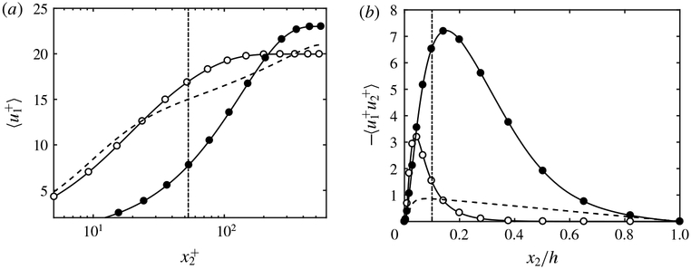
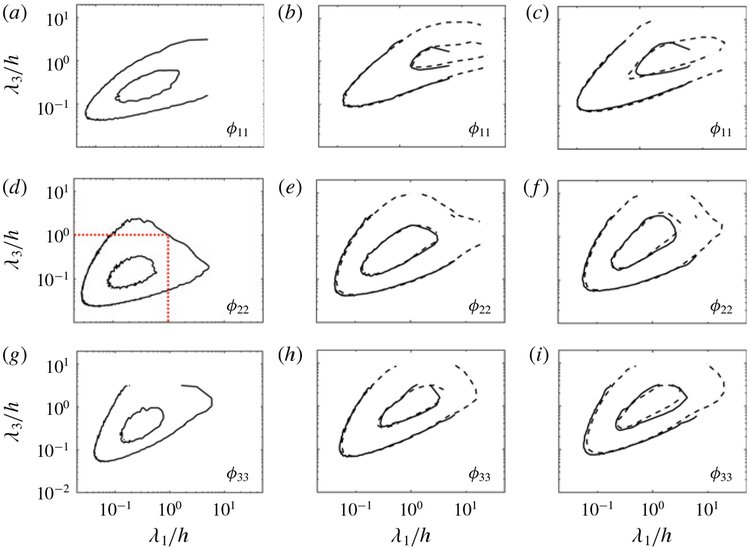
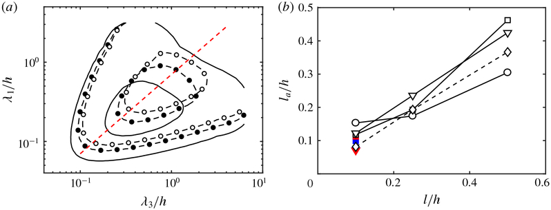
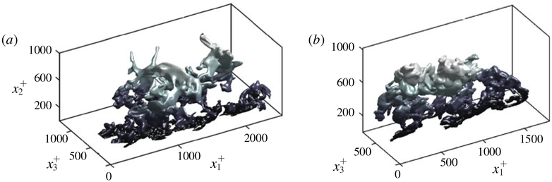
Townsend (The Structure of Turbulent Shear Flow, 1976, Cambridge University Press) proposed a structural model for the logarithmic layer (log layer) of wall turbulence at high Reynolds numbers, where the dominant momentum-carrying motions are organised into a multiscale population of eddies attached to the wall. In the attached-eddy framework, the relevant length and velocity scales of the wall-attached eddies are the friction velocity and the distance to the wall. In the present work, we hypothesise that the momentum-carrying eddies are controlled by the mean momentum flux and mean shear with no explicit reference to the distance to the wall and propose new characteristic velocity, length and time scales consistent with this argument. Our hypothesis is supported by direct numerical simulation of turbulent channel flows driven by non-uniform body forces and modified mean velocity profiles, where the resulting outer-layer flow structures are substantially altered to accommodate the new mean momentum transfer. The proposed scaling is further corroborated by simulations where the no-slip wall is replaced by a Robin boundary condition for the three velocity components, allowing for substantial wall-normal transpiration at all length scales. We show that the outer-layer one-point statistics and spectra of this channel with transpiration agree quantitatively with those of its wall-bounded counterpart. The results reveal that the wall-parallel no-slip condition is not required to recover classic wall-bounded turbulence far from the wall and, more importantly, neither is the impermeability condition at the wall.

Keywords: turbulence simulation; turbulence theory; turbulent boundary layers.


Figures

Figure 1.
Figure 1.
(Colour online) Sketch of wall-attached momentum-carrying eddies of different sizes in a turbulent boundary layer controlled by the mean production rate of turbulent kinetic energy, −〈u1u2〉∂〈u1〉/∂x2, and proposed velocity u*, time t* and length l* scales.
Figure 2.
Figure 2.
Mean (a) total tangential Reynolds stress and (b) streamwise velocity profile for NS550 (– – –), NS550-p (O) and NS550-n (●). Panels (c,d) contain the streamwise (circles and – – –), wall-normal (triangles and – – –) and spanwise (squares and ⋯ ⋯) r.m.s. velocity fluctuations scaled with (c) uτ and (d) u. Symbols are for NS550-p (open) and NS550-n (closed). Lines without symbols are for NS550. For clarity, the profiles for the wall-normal and spanwise r.m.s. velocity fluctuations are shifted vertically by 2.0 and 3.4 wall units.
Figure 3.
Figure 3.
Mean (a) streamwise velocity profile and (b) tangential Reynolds stress for NS550 (– – –), NS550-s1 (O) and NS550-s2 (●). The dash-dotted line is x2 = 0.1h.
Figure 4.
Figure 4.
(Colour online) Premultiplied streamwise ϕ11 (a,d), wall-normal ϕ22 (b,e) and spanwise ϕ33 (c,f) velocity two-dimensional spectra at x2 = 0.10h for NS550 (——), NS550-s1 (O) and NS550-s2 (●). The wavelengths are scaled by x2 in (a–c) and by l* in (df). Contours are 0.1 and 0.6 of the maximum.
Figure 5.
Figure 5.
(Colour online) Premultiplied streamwise ϕ11 (a,d,g), wall-normal ϕ22 (b,e,h) and spanwise ϕ33 (c,f,i) two-dimensional velocity spectra at x2/h = 0.10, 0.15, 0.20, 0.30 and 0.40 (from black to red) for NS2000. The wavelengths are scaled by h (ac), x2 (df) and l* (gi). Contours are 0.1 and 0.6 of the maximum. The arrows in panels (ac) indicate increasing distance from the wall.
Figure 6.
Figure 6.
(Colour online) (a) Mean tangential Reynolds stress as a function of the wall-normal (or boundary-normal) coordinate for R550 (O), R950 (▼), R2000 (□), NS550 (– – –), NS950 (– – –) and NS2000 (⋯ ⋯). (b) Premultiplied boundary-normal two-dimensional velocity spectra for Robin-bounded channels at x2/h = 0. Contours are 0.1 and 0.6 of the maximum. The red dashed lines are λ1/h = 1 and λ3/h = 1. Symbols are as in panel (a).
Figure 7.
Figure 7.
(Colour online) Instantaneous x1x2 planes of the streamwise (a,b), wall-normal (c,d) and spanwise (e,f) velocities for turbulent channels at Reτ = 2000. (a,c,e) are for R2000, and (b,d,f) are for NS2000. The colour bars show velocity in wall units.
Figure 8.
Figure 8.
Mean streamwise velocity profiles as a function of x2 in (a) linear scale and (b) logarithmic scale for R550 (O), R950 (∇), R2000 (□), NS550 (– – –), NS950 (– - – -) and NS2000 (⋯ ⋯). In panel (b), the velocity profiles of Robin-bounded cases are vertically shifted such that the centreline velocity coincides with their corresponding wall-bounded case. For clarity, profiles at Reτ ≈ 950 and Reτ ≈ 2000 are additionally shifted by 5 and 10 plus units, respectively.
Figure 9.
Figure 9.
(a) Streamwise, (b) wall-normal (or boundary-normal) and (c) spanwise r.m.s. velocity fluctuations, and (d) r.m.s. pressure fluctuations for R550 (O), R950 (∇), R2000 (□), NS550 (– – –), NS950 (– - – -) and NS2000 (⋯ ⋯). In all panels, the profiles for cases at Reτ ≈ 950 and Reτ ≈ 2000 are vertically shifted by 0.5 and 1 plus units, respectively, for clarity.
Figure 10.
Figure 10.
(Colour online) Wall-parallel premultiplied streamwise (ac), wall-normal (or boundary-normal) (df) and spanwise (gi) velocity spectra for R2000 (——) and NS2000 (– – –). The wall-normal (or boundary-normal) locations are x2+=0 (a,d,g), x2+=1001 (b,e,h) and x2+=2003 (c,f,i). Contours are 0.1 and 0.6 of the maximum. The red dotted lines in (d) are λ1/h = 1 and λ3/h = 1.
Figure 11.
Figure 11.
(Colour online) (a) Wall-parallel premultiplied boundary-normal velocity spectra at x2+=0 for R550 (——), R550-l1 (O) and R550-l2 (●). Contours are 0.1 and 0.6 of the maximum. The red dashed line is λ3 = 0.7λ1. (b) Adaptation length la for the mean velocity profile (◇), and r.m.s. streamwise (O), boundary-normal (□) and spanwise (∇) velocity fluctuations as a function of the slip length l. Colours are black for R550, blue for R950 and red for R2000.
Figure 12.
Figure 12.
(Colour online) (a) Kolmogorov length scale η for NS550 (– – –) and R550 (O), and integral length scale Lε for NS550 (——), R550 (□), R950 (◇) and R2000 (Δ). (b) l as a function of Reτ. Closed and open symbols are for wall-bounded and Robin-bounded cases, respectively. The dashed line is El+~Reτ1.
Figure 13.
Figure 13.
(Colour online) Example of instantaneous three-dimensional momentum transfer structures extracted from R2000 (a) and NS2000 (b). The mean flow is from bottom left to top right. Axes are normalised in plus units. The colour gradient indicates distance to the wall/boundary.
Figure 14.
Figure 14.
(Colour online) Joint p.d.f.s of the logarithms of the box sizes of structures, (a) p(Δ1+,Δ2+) and (b) p(Δ3+,Δ2+), for NS2000 (——) and R2000 (– – –). Contours contain 50% and 99.8% of the p.d.f. The dashed straight lines are Δ1 = 1.5Δ2 and Δ1 = Δ3, respectively.
Figure 15.
Figure 15.
Streamwise (circles and – – –), wall-normal (triangles and – – –) and spanwise (squares and ⋯ ⋯) r.m.s. velocity fluctuations scaled with u*. Symbols are for NS550-p (open) and NS550-n (closed). Lines without symbols are for NS550. For clarity, the profiles for the wall-normal and spanwise r.m.s. velocity fluctuations are shifted vertically by 2.0 and 3.4 wall units.
Figure 16.
Figure 16.
(Colour online) Instantaneous x1x3 planes of the (a) streamwise, (b) wall-normal and (c) spanwise velocity for R2000 at x2/h = 0. The mean flow is from left to right. The colour bars show velocity normalised in wall units.
Figure 17.
Figure 17.
Streamwise (O), wall-normal (□) and spanwise (Δ) r.m.s. fluctuating velocities at x2/h = 0 for Robin-bounded cases as a function of (a) slip length and (b) friction Reynolds number.
Figure 18.
Figure 18.
(Colour online) Wall-parallel (x1x3) correlations of the (a) streamwise, (b) wall-normal and (c) spanwise velocity for R550 (——), R950 (– – –), R2000 (– - – -) and R550-l1 (⋯ ⋯). Contours are 0.05 and 0.5 of the maximum value. The mean flow is from left to right.
Figure 19.
Figure 19.
(Colour online) (a) Diagnostic function Ξ=x2u1/x2 for NS550 (∇), NS950 (O), R550-lplus (– – –) and R950-lplus (⋯ ⋯). (b) Plot of l2 as a function of Reτ for wall-bounded cases NS550 and NS950 (O), and Robin-bounded cases R550-lplus and R950-lplus (×).

References

    1. Abderrahaman-Elena N & García-Mayoral R 2017. Analysis of anisotropically permeable surfaces for turbulent drag reduction. Phys. Rev. Fluids 2, 114609.
    1. Adrian RJ 2007. Hairpin vortex organization in wall turbulence. Phys. Fluids 19 (4), 041301.
    1. Adrian RJ, Meinhart CD & Tomkins CD 2000. Vortex organization in the outer region of the turbulent boundary layer. J. Fluid Mech. 422, 1–54.
    1. Afzal N 1976. Millikan’s argument at moderately large Reynolds number. Phys. Fluids 19 (4), 600–602.
    1. Afzal N & Yajnik K 1973. Analysis of turbulent pipe and channel flows at moderately large Reynolds number. J. Fluid Mech. 61 (1), 23–31.

LinkOut - more resources