. 2019 Oct 25;14(10):e0221850.
doi: 10.1371/journal.pone.0221850. eCollection 2019.

Variation in bone response to the placement of percutaneous osseointegrated endoprostheses: A 24-month follow-up in sheep

Affiliations

Variation in bone response to the placement of percutaneous osseointegrated endoprostheses: A 24-month follow-up in sheep

Sujee Jeyapalina et al. PLoS One. .

Abstract

Percutaneous osseointegrated (OI) devices for amputees are metallic endoprostheses, that are surgically implanted into the residual stump bone and protrude through the skin, allowing attachment of an exoprosthetic limb. In contrast to standard socket suspension systems, these percutaneous OI devices provide superior attachment platforms for artificial limbs. However, bone adaptation, which includes atrophy and/or hypertrophy along the extent of the host bone-endoprosthetic interface, is seen clinically and depends upon where along the bone the device ultimately transfers loading forces to the skeletal system. The goal of this study was to determine if a percutaneous OI device, designed with a porous coated distal region and an end-loading collar, could promote and maintain stable bone attachment. A total of eight, 18 to 24-month old, mixed-breed sheep were surgically implanted with a percutaneous OI device. For 24-months, the animals were allowed to bear weight as tolerated and were monitored for signs of bone remodelling. At necropsy, the endoprosthesis and the surrounding tissues were harvested, radiographically imaged, and histomorphometrically analyzed to determine the periprosthetic bone adaptation in five animals. Bone growth into the porous coating was achieved in all five animals. Serial radiographic data showed stress-shielding related bone adaptation occurs based on the placement of the endoprosthetic stem. When collar placement and achieved end-bearing against the transected bone, distal bone conservation/hypertrophy was observed. The results supported the use of a distally loading and distally porous coated percutaneous OI device to achieve distal host bone maintenance.


Conflict of interest statement

The authors have declared that no competing interests exist.

Figures
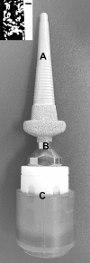
Fig 1
Fig 1
A photograph of the sheep percutaneous OI device showing endoprosthesis (A), percutaneous post (B) and exoprosthetic hoof (C). Inset is the cross-sectional electron backscattering image showing the thickness of the porous commercially pure titanium coating (~1 mm). White–metal. Black–pores. Scale bar—300 μm.
Fig 2
Fig 2
AP and ML radiographs of the metacarpal from the animal that developed clinical signs of infection ((a)—taken Post-Surgery and (b)–taken Post-Necropsy). Radiographs showed pronounced radiolucent zones medial, lateral and anterior to the endoprosthetic device (white arrows) and show periosteal reactive bone responses (*), a common sign of infection. Subsequent histological imaging verified a sub-periosteal infection (cross-sections stained with Sanderson Rapid Bone stain ((c), (d), and (e)); Pink-mineralized tissue and blue-fibrous tissue). Woven-bone exiting the periosteal surface is the reactive bone formation equivalent to sequestrum formation seen in the presence of chronic infection. Yellow arrows point to osteoclasts.
Fig 3
Fig 3. Representative BSE photomicrographs showing bone ingrowth into the porous-coated region of the five animals (X50 original magnification).
In cross-sections of Animals A, B, and C, bone ingrowth is pronounced and mineralized. In cross-sections of Animals D and E, while there is bone ingrowth, there is also evidence of periprosthetic resorption, which is likely due to adaptation of stress shielded bone. Scale bar = 500μm. Porous coating; gray = bone; black = soft tissues, marrow, and cellular components.
Fig 4
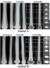
Fig 4. Serial radiographs taken at post-surgery (“Time 0”), at 6-month follow-up and at necropsy, 24-months post-implantation for Animal A and Animal D.
Each panel shows AP view and ML view for each animal. Cross-sectional images in the far-right panel were acquired from μ-CT taken at 24-months post-surgery. Sections (a) from the proximal region through section (f) at the most distal region. Radiographs from Animal “A” show an endoprosthesis with an ideal end bearing fitting; Radiographs from Animal “D” show an endoprosthesis that was tightly bound in the proximal medullary canal. This resulted in distal bone resorption.
Fig 5
Fig 5
Cross-sectional images of a non-implanted control animal with representative bone-endoprosthesis cross-sections of the five experimental animals (A-E), stained with Sanderson Rapid Bone Stain. Sections were taken from different regions along the length of the endoprosthesis. The top row shows images from the smooth region of the endoprostheses, see Fig 4, Regions (a) or (b) or (c). The middle row shows images from the fluted regions of the endoprostheses, see Fig 4, Regions (d) or (e). The bottom row shows images from the porous coated region, of the endoprostheses, see Fig 4, Region (f). At surgery, the porous coated region was impacted into the cancellous metaphyseal bone. Pink = mineralized tissue (bone), black = endoprosthesis and blue = fibrous tissue. Scale bar = 3mm.
Fig 6
Fig 6. Photomicrographs showing the proximal end of the endoprosthesis-bone-interface.
In 6-, 9-, and 12-month animals, the majority of the sites showed an interposing fibrous capsule (blue) between the implant (black) and the bone (pink).
Fig 7
Fig 7. Photomicrograph of representative bone-endoprosthesis stem interface stained with Sanderson rapid bone stain: Black = endoprosthesis, pink = bone and blue = fibrous tissue.
Scale bar = 1000 μm.

References

    1. Al Muderis M, Khemka A, Lord SJ, Van de Meent H, Frolke JP. Safety of Osseointegrated Implants for Transfemoral Amputees: A Two-Center Prospective Cohort Study. J Bone Joint Surg Am. 2016;98(11):900–9. 10.2106/JBJS.15.00808 . - DOI - PubMed
    1. Branemark R, Berlin O, Hagberg K, Bergh P, Gunterberg B, Rydevik B. A novel osseointegrated percutaneous prosthetic system for the treatment of patients with transfemoral amputation: A prospective study of 51 patients. Bone Joint J. 2014;96-B(1):106–13. 10.1302/0301-620X.96B1.31905 . - DOI - PubMed
    1. Hagberg K, Branemark R. One hundred patients treated with osseointegrated transfemoral amputation prostheses—rehabilitation perspective. J Rehabil Res Dev. 2009;46(3):331–44. Epub 2009/08/14. . - PubMed
    1. Juhnke DL, Beck JP, Jeyapalina S, Aschoff HH. Fifteen years of experience with Integral-Leg-Prosthesis: Cohort study of artificial limb attachment system. J Rehabil Res Dev. 2015;52(4):407–20. Epub 2015/09/09. 10.1682/JRRD.2014.11.0280 . - DOI - PubMed
    1. Van de Meent H, Hopman MT, Frolke JP. Walking ability and quality of life in subjects with transfemoral amputation: a comparison of osseointegration with socket prostheses. Arch Phys Med Rehabil. 2013;94(11):2174–8. 10.1016/j.apmr.2013.05.020 . - DOI - PubMed

Publication types