Review
. 2019 Oct 10;19(20):4376.
doi: 10.3390/s19204376.

Recent Advances in Skin Chemical Sensors

Affiliations
Review

Recent Advances in Skin Chemical Sensors

Benoît Piro et al. Sensors (Basel). .

Abstract

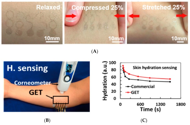
This review summarizes the latest developments in the field of skin chemical sensors, in particular wearable ones. Five major applications are covered in the present work: (i) sweat analysis, (ii) skin hydration, (iii) skin wounds, (iv) perspiration of volatile organic compounds, and (v) general skin conditions. For each application, the detection of the most relevant analytes is described in terms of transduction principles and sensor performances. Special attention is paid to the biological fluid collection and storage and devices are also analyzed in terms of reusability and lifetime. This review highlights the existing gaps between current performances and those needed to promote effective commercialization of sensors; future developments are also proposed.

Keywords: diabetes; flexible; printed electronics; skin sensors; smart dressings; smart tattoos; sweat; wearable.


Conflict of interest statement

The author declares no conflict of interest. The founding sponsors had no role in the design of the study; in the collection, analyses, or interpretation of data and in the writing of the manuscript.

Figures

Figure 1
Figure 1
(A) Image of the gold electrodes array on a polymeric wound dressing. (B) Pictures of a transferred printed flexible array, fixed with a liquid bandage, under mechanical stress. Reproduced from [27] with permission. Copyright 2019 Elsevier B.V.
Figure 2
Figure 2
(A) PMMA patch onto which the microfluidic channels and reservoir are engraved. The printed patterns are used as visual references. (B) Soft PDMS patch for collecting sweat. The width and depth of the coiled channel are 1 mm and 300 μm, respectively. (C) Patch placed close to the armpit. Some sweat (internally mixed with a dark dye) started to flow. (D) Exploded view of the patch. (E) Example of data transmission by image treatment using a smartphone. Reproduced from [28] with permission. Copyright © 2019, American Chemical Society.
Figure 3
Figure 3
(A) Exploded view of the colorimetric/amperometric device. PI: polyimide. S.R.: sweat rate. (B) Colorimetric and microfluidic parts of the patch upon bending and (C) NFC electronics (D) that are placed on top of the patch. (E,F) Complete device into a hand and fixed on a forearm. (G) Illustration of a smartphone application for wireless communication with the patch. Reproduced from [30]. Copyright © 2019 The Authors, some rights reserved. Distributed under a Creative Commons Attribution Non-Commercial License 4.0 (CC BY-NC).
Figure 4
Figure 4
(A) General scheme of an OECT. All components are in PEDOT:PSS. (B) Screen-printed OECTs (devices on the left, fabricated on woven cotton (250 μm thick) and those on the right printed on a Lycra substrate). Reproduced from [31]. Creative Commons Attribution 4.0 International License. Copyright 2016 Springer Nature Publishing AG.
Figure 5
Figure 5
Patterned paper fish under various mechanical stresses. Reproduced from [32] with permission. Copyright 2018 WILEY-VCH Verlag GmbH & Co. KGaA, Weinheim.
Figure 6
Figure 6
(A) Scheme of the four layers constituting the microfluidic chip (PSA: pressure sensitive adhesive). (B) Place where the patch is attached to the subject during an effort; inset: detail of the patch. (C) Measured lactate and (D) sodium cations in sweat during an effort. Adapted from [33]. Creative Commons Attribution License (CC BY), 2017.
Figure 7
Figure 7
(A) Microfluidic electrochemical patch with (1) Gold current collectors lithographied then transferred on the PDMS substrate; (2,3) Reference (RE) screen-printed with silver/silver chloride (Ag/AgCl), working (WE) and counter (CE) electrodes screen-printed with Prussian blue; (4) PDMS microfluidic layer finally bonded (5) on top of the PDMS electrode layer. (B) View of the complete patch glued on skin, as a function of time during effort. Sweat is mixed with a blue dye inside the device for this picture. Reproduced from [34] with permission. Copyright © 2017, American Chemical Society.
Figure 8
Figure 8
(A) Depiction of two different wearable epidermal glucose sensors using the interstitial fluid (ISF) or sweat. (B) Basic functioning of the enzymatic amperometric glucose sensor. Reproduced from [35] with permission. © 2017 Elsevier B.V. All rights reserved. (C) Glucose sensing in ISF through reverse iontophoresis (bottom-right) and GlucoWatch® biographer display. Reproduced from [36] with permission. Copyright © 2002 John Wiley & Sons, Ltd. Left: reverse iontophoresis process. Reproduced from [37] with permission. Copyright © 2001 Elsevier Science B.V. All rights reserved. (D) Top: Picture of a flexible sweat extraction and sensing device along with the data-treatment electronics on a flexible board. Bottom: iontophoresis and sensing mode of operation. Reproduced from [38] with permission. Copyright 2017, National Academy of Sciences.
Figure 8
Figure 8
(A) Depiction of two different wearable epidermal glucose sensors using the interstitial fluid (ISF) or sweat. (B) Basic functioning of the enzymatic amperometric glucose sensor. Reproduced from [35] with permission. © 2017 Elsevier B.V. All rights reserved. (C) Glucose sensing in ISF through reverse iontophoresis (bottom-right) and GlucoWatch® biographer display. Reproduced from [36] with permission. Copyright © 2002 John Wiley & Sons, Ltd. Left: reverse iontophoresis process. Reproduced from [37] with permission. Copyright © 2001 Elsevier Science B.V. All rights reserved. (D) Top: Picture of a flexible sweat extraction and sensing device along with the data-treatment electronics on a flexible board. Bottom: iontophoresis and sensing mode of operation. Reproduced from [38] with permission. Copyright 2017, National Academy of Sciences.
Figure 9
Figure 9
(A) Scheme of iontophoretic delivery of pilocarpine and iontophoretic extraction of glucose. (B) Screen-printed biosensor coupled with wireless flexible printed circuit board. The left-hand site is dedicated to alcohol sensing while the right-hand side is dedicated to glucose. White scale bar: 7 mm. (C) Demonstration of the flexibility of the overall device (board + sensors). (D) Tattooing the sensor part. (E) Sensing performance after meal then alcohol intake (left) or alcohol then meal intake, compared with blood glucose and breath alcohol. Reproduced from [39]. © 2018 the authors. Published by WILEY-VCH Verlag GmbH & Co. KGaA, Weinheim. https://creativecommons.org/licenses/by/4.0/.
Figure 9
Figure 9
(A) Scheme of iontophoretic delivery of pilocarpine and iontophoretic extraction of glucose. (B) Screen-printed biosensor coupled with wireless flexible printed circuit board. The left-hand site is dedicated to alcohol sensing while the right-hand side is dedicated to glucose. White scale bar: 7 mm. (C) Demonstration of the flexibility of the overall device (board + sensors). (D) Tattooing the sensor part. (E) Sensing performance after meal then alcohol intake (left) or alcohol then meal intake, compared with blood glucose and breath alcohol. Reproduced from [39]. © 2018 the authors. Published by WILEY-VCH Verlag GmbH & Co. KGaA, Weinheim. https://creativecommons.org/licenses/by/4.0/.
Figure 10
Figure 10
(A,B) Flexible patch and its transfer on skin. (C) Sweat generation with the wearable patch on the subject’s arm. Reproduced from [40]. Copyright © 2017, The Authors. Creative Commons Attribution-NonCommercial license. (D) Comparison between the patch, a glucose strip, and continuous glucose monitoring (CGM) over the course of a day. Reproduced from [41] with permission. Copyright © 2016, Springer Nature.
Figure 10
Figure 10
(A,B) Flexible patch and its transfer on skin. (C) Sweat generation with the wearable patch on the subject’s arm. Reproduced from [40]. Copyright © 2017, The Authors. Creative Commons Attribution-NonCommercial license. (D) Comparison between the patch, a glucose strip, and continuous glucose monitoring (CGM) over the course of a day. Reproduced from [41] with permission. Copyright © 2016, Springer Nature.
Figure 11
Figure 11
(A) Correlation in ratios of glucose content after glucose loading to the corresponding value before loading, for sweat and blood. Pearson coefficient r = 0.75. (B) Normalized sweat glucose level (solid lines) in comparison with blood vein glucose (circles) during a glucose tolerance test. The black and white circles correspond to two different measures. Curve 2 was obtained on a patient whose sweat has not been stimulated beforehand (sweat stimulation took about 25 min), while curve 1 was obtained on a patient whose sweat has been stimulated well before the glucose test. The breaks in the curves correspond to a second sweat stimulation. Reproduced from [45] with permission. Copyright © 2019 American Chemical Society.
Figure 12
Figure 12
(A) Scheme of the three-layer device: (i) top PDMS layer carrying sensing electrodes; (ii) middle PDMS layer carrying microfluidics; (iii) adhesive layer in contact with the skin. (B) Sweat collection. (C) Device integrated with wireless flexible electronics. Scale bar: 5 mm. (D) Position of the sensor on the back of the subject during effort. (E) Continuous lactate monitoring with (blue full line) and without (dotted line) lactate oxidase for (i) subject 1 and (ii) subject 2. (F) Continuous glucose monitoring before (red full line) and after meal (black full line) with glucose oxidase and without (dotted line) for (i) subject 1 and (ii) subject 2. Amperometric experiments were carried out at −0.1 V vs. Ag/AgCl during physical exercise, and all data were wirelessly transmitted to a computer. Reproduced from [34] with permission. Copyright © 2017 American Chemical Society.
Figure 13
Figure 13
(A) View of the agarose-based lactate sensor. (B) Potentiometric response of the lactate oxidase modified sensor upon subject’s forefinger contact. Reproduced from [48]. http://creativecommons.org/licenses/by/4.0/.
Figure 14
Figure 14
(A) Picture of the front and back sides (left, middle) of the sensor array with contacts, conductive tracks and electrodes (pH, lactate, and glucose). Right: Sensor wristband on subject’s forearm. (B) Stretching in both directions and rolling up. (C) Patterned underlayer for sweat collection. This layer, which is put in direct contact with the skin, is the backside of the sensors layer. (D) Glucose, pH, and lactate monitoring on a subject’s forearm before and after meal, and during effort (maximum effort at 20 min). Reproduced from [54] with permission. © 2019 WILEY-VCH Verlag GmbH & Co. KGaA, Weinheim.
Figure 15
Figure 15
Pictures of the chrono-sampling of sweat (artificially colored in blue), introduced at a rate of 10 μL min−1. The different areas are filled sequentially with the colored sweat solution depending on the swollen state of the superabsorbent polymer (SAP) valve. Reproduced from [56] with permission. © 2018 WILEY-VCH Verlag GmbH & Co. KGaA, Weinheim.
Figure 16
Figure 16
(A) Picture of the whole device (left) and schematic view of microfluidic chambers and channels into which are integrated the ion selective electrodes (right). (B) Simultaneous recording of the ISE potentials for Na+ and K+ for a sensor mounted on the shoulder of a bicycle pedaling subject. Reproduced from [58] with permission. © 2019 Wiley-VCH Verlag GmbH & Co. KGaA, Weinheim.
Figure 17
Figure 17
(A) Schematic of the sensor array, showing glucose, lactate, sodium, potassium and temperature sensors. (B) Photograph of a flattened flexible PCB, with the sensors array on the left, and the 11 electronic components on the right. (C) Picture of the active wristlet on a subject’s wrist. (D) Real-time sweat sodium and potassium levels during an endurance run with (left) or without (right) water intake. Dehydration is diagnosed in the latter case. Reproduced from [59] with permission. Copyright © 2016, Springer Nature.
Figure 18
Figure 18
(A) Scheme of the manufacturing process on a polyurethane (PU) substrate. (B) Examples of use of the sensor, on underwear, wristband, and headband, illustrating the versatility of the printable and stretchable sensor array on different common wearable objects. The tablet displays a real-time trace of increasing potassium levels obtained wirelessly by the underwear printed sensor. Reproduced from [60] with permission. © 2016 WILEY-VCH Verlag GmbH & Co. KGaA, Weinheim.
Figure 19
Figure 19
(a) Photograph of the stretchable wireless antenna, data transmission circuit and sensor. Right: steps of the transfer protocol of the circuits from Si wafer to PDMS. Reproduced from [63] with permission. © 2018 Elsevier B.V. All rights reserved.
Figure 20
Figure 20
(A) a—Scheme of the flexible strip integrating pH and temperature sensors; b—Side view of the encapsulated sensors; c—Picture of the strip held between two fingers. d, e—Details of the two sensors. (B) Real-time pH and skin temperature acquired from the neck of a patient, by the device (continuous lines) and measured by commercial pH and infrared sensors (squares and circles). (C) a—Picture of the complete strip under bending (r: curvature radius). b, c—Normalized ISFET current as a function of curvature radius and during 1600 bending cycles at a radius of 32.5 mm. Reproduced from [64]. Copyright © 2017, American Chemical Society.
Figure 21
Figure 21
(A) Illustration of the Si-NC-based humidity sensor. (B) Current of the sensor as a function of relative humidity. Open and filled marks: increasing and decreasing humidity, respectively. (C) Illustration of charge carrier transport principle on Si-NC. (D) Monitoring of water evaporation from a bare hand skin. (E) Real-time detection of water evaporation from a hand. Pink periods correspond to application of a bare hand on the sensor. Reproduced from [67] with permission. Copyright © 2017, American Chemical Society.
Figure 22
Figure 22
(A) Graphene based electronic tattoo mounted on skin. (B) Demonstration of the graphene electronic tattoo (GET) sensor as skin hydration sensor, compared to a commercial corneometer. (C) Skin hydration after application of body lotion, using the humidity sensor of the GET and the commercial corneometer. Reproduced from [69] with permission. Copyright © 2017, American Chemical Society.
Figure 23
Figure 23
(A) Fabrication of the silver nanowires (AgNW)-based sensor, with AgNW network before being embedded into PDMS (left SEM picture) and after embedding (right SEM picture). (B) Picture of an AgNW patch placed on the inner side of a forearm. (C) Impedance changes from real human skin before and after applying a hydration lotion. (D) Skin impedance extracted from (C), at 100 kHz before and after applying the lotion. Reproduced from [70] with permission. © 2017 WILEY-VCH Verlag GmbH & Co. KGaA, Weinheim.
Figure 23
Figure 23
(A) Fabrication of the silver nanowires (AgNW)-based sensor, with AgNW network before being embedded into PDMS (left SEM picture) and after embedding (right SEM picture). (B) Picture of an AgNW patch placed on the inner side of a forearm. (C) Impedance changes from real human skin before and after applying a hydration lotion. (D) Skin impedance extracted from (C), at 100 kHz before and after applying the lotion. Reproduced from [70] with permission. © 2017 WILEY-VCH Verlag GmbH & Co. KGaA, Weinheim.
Figure 24
Figure 24
(A) (a) commercial Allevyn™ dressing mounted with tube, for injection of simulated exudates (obviously not intended for use on real patients). (b) Dressing and sensors in place on leg, before bandage application. (c) Bandage covering the whole device. (d) Dressing and sensors immediately after removal of bandages (the simulate exudate stain is clearly visible). (B) Measurement of moisture using the compression bandage shown in (a). Reproduced from [75]. Creative Commons Attribution License 4.0.
Figure 25
Figure 25
(A) WoundSense electrodes in direct contact with the wound, before dressing and (B) after dressing. (C) The WoundSense™ commercial meter. Reproduced from [77] with permission. © 2015 the authors. International Wound Journal published by Medicalhelplines.com Inc and John Wiley & Sons Ltd. Creative Commons Attribution-NonCommercial-NoDerivs Licence.
Figure 26
Figure 26
Oxidation products of a peptide homopolymer of tryptophan. After a first electrooxidation step, the fibers become electroactive due to the presence of the para- and orthoquinone groups. Reproduced from [79]. Creative Commons Attribution License.
Figure 27
Figure 27
(A) Plots show the effects of pH on the specific activity of UOx. The red diamond markers denote higher activity of urate oxidase (UOx). The inset image represents the relationship between the wound healing stages and pH. (B) Screen-printed graphite + UA electrode on a dressing. (C) Experimental setup. Reproduced from [81]. © the author(s) 2018. Published by ECS. http://creativecommons.org/licenses/by/4.0/.
Figure 28
Figure 28
The three wound healing stages: (A) inflammation, (B) proliferation, and (C) remodeling. Reproduced from [89] with permission. Copyright © 2008, Springer Nature. (D) The general implementation and operation of a smart dressing. Reproduced from [79] Creative Commons Attribution License.
Figure 29
Figure 29
(A) Scheme of the various parts of the device (right: picture with contact electrodes). (B) Overall reactions involved in the sensing mechanism, which involves alcohol oxidase (AOD), a second enzyme (horse radish peroxidase—HRP) and ferrocene as mediator. (C) Correlation between the device output signal and blood alcohol concentration (BAC) values: (■) values measured with the biodevice in the single measurement mode, (○) values measured with the biodevice in the single measurement mode at 5 min (in both cases: n = 40 subjects). The straight lines show the corresponding BAC intervals obtained by the gas chromatography method. Reproduced from [91] with permission. Copyright © 2013 Elsevier B.V. All rights reserved.
Figure 30
Figure 30
(A) Scheme of the iontophoretic flexible device, with the iontophoretic electrodes and the sensing electrodes. (B) Picture of the whole system (sensor with electronics) applied on the forearm of a subject. (C) Picture of the flexible wireless electronics. (D) Scheme of the constituents in the iontophoretic system (left) and in the amperometric electrode (right). (E) Experiments performed before (plot ‘a’) and after (plot ‘b’) consumption of 350 mL of beer measured on two different human subjects. Reproduced from [92] with permission. Copyright © 2016, American Chemical Society.
Figure 30
Figure 30
(A) Scheme of the iontophoretic flexible device, with the iontophoretic electrodes and the sensing electrodes. (B) Picture of the whole system (sensor with electronics) applied on the forearm of a subject. (C) Picture of the flexible wireless electronics. (D) Scheme of the constituents in the iontophoretic system (left) and in the amperometric electrode (right). (E) Experiments performed before (plot ‘a’) and after (plot ‘b’) consumption of 350 mL of beer measured on two different human subjects. Reproduced from [92] with permission. Copyright © 2016, American Chemical Society.
Figure 31
Figure 31
(A) The wristband sensor with its disposable cartridge (a); Scheme of the disposable sensor’s components (b); Amperometric detection principle, using alcohol oxidase and Prussian blue. (B) Current measurements using the developed device (grey) and derived equivalent blood alcohol concentration (black), for two periods of 24 h, interrupted by the necessary change of the disposable cartridge. Reproduced from [93]. Creative Commons Attribution License.
Figure 32
Figure 32
(A) Wristband carrying the SnO2 sensor and the electronics associated to it. (B) Comparison of blood (BAC), breath (BrAC) and transdermal (TAC) alcohol concentration for a maximum BAC of 0.5 g L−1. (C) Comparison of BAC, BrAC, and TAC for a maximum BAC of 0.5 g L−1. Reproduced from [94] with permission. © 2018 Elsevier B.V. All rights reserved.
Figure 33
Figure 33
(A) Schematics of the potentiometric tattoo sensor working mechanism showing organophosphate hydrolysis on the OPH-modified electrode. Protons are released and protonate the polyaniline (PANi) layer. The data are transmitted wirelessly. The Ag/AgCl reference electrode is protected by a polyvinylbenzene (PVB) membrane containing NaCl. (B) Sensor transfer to the skin. (C) Resistance of the tattoo to mechanical strains. Reproduced from [96] with permission. © 2018 Elsevier B.V. All rights reserved.
Figure 34
Figure 34
(A) Left: scheme and dimensions of the tattoo electrodes; Right: tattoo electrodes as applied on the inner forearm. (B) Side-profile scheme of the electrical field from the tattoo electrodes across the stratum corneum (SC). Reproduced from [98] with permission. © 2017 Wiley-VCH Verlag GmbH & Co. KGaA, Weinheim.
Figure 35
Figure 35
(A) Images of the thin flexible device upon stretching on skin, for (a) silver electrodes only, (b) silver + elastomer, (c) silver electrodes + porous acrylate adhesive and (d) silver + elastomer electrodes + porous acrylate adhesive. (B) Impedance (Nyquist plot) of the inner forearm, measured by the silver-elastomer tattoo device. Reproduced from [99] with permission from The Royal Society of Chemistry.
Figure 36
Figure 36
(A) (left) Scheme of the whole epidermis; (right) oxygen electrode covered with viable pig skin, used in this study. (B) Current delivered by the skin-covered oxygen electrode when immersed in phosphate buffer saline + sequential H2O2 addition. The catalase enzyme contained in the skin transforms H2O2 into O2, which diffuses back to the electrode. Azide, as catalase inhibitor, is added to attest that the current is due to the enzyme activity. Reproduced from [100] with permission. © 2017 Elsevier B.V. All rights reserved.
Figure 37
Figure 37
(A) The patch (100) claimed by [105] is based on cellulose fibers comprising radial channels (102) for sweat collection, carrying dyes at the end of the channels (104) for reading, and made of a wicking material (106) such as cellulose acetate or nitrocellulose laminated between two polymer films. The central collecting region (108) is made of the same material. (B) Wristband device claimed by Lansdorp et al. [106]. (100): whole device; (102) wristband; (104): wristband fastener; (106) sensor cartridge; (108) device body containing electronics.
Figure 38
Figure 38
(A) Application of the settable material on the face of the subject. This settable material includes bacteria-sensitive regions. (B) After removing, the inner part of the mask (carrying the ELISA sensing layer) is analyzed with a camera which maps (C) the various regions of the subject’s face and quantify the bacteriome on each area. Ref. [107].

References

    1. Almansoori M.T., Li X., Zheng L. A Brief Review on E-skin and its Multifunctional Sensing Applications. Curr. Smart Mater. 2019;4:3–14. doi: 10.2174/2405465804666190313154903. - DOI
    1. Kim S.Y., Park S., Park H.W., Park D.H., Jeong Y., Kim D.H. Highly Sensitive and Multimodal All-Carbon Skin Sensors Capable of Simultaneously Detecting Tactile and Biological Stimuli. Adv. Mater. 2015;27:4178–4185. doi: 10.1002/adma.201501408. - DOI - PubMed
    1. Amjadi M., Kyung K.U., Park I., Sitti M., Kyung K.U., Kyung K. Stretchable, Skin-Mountable, and Wearable Strain Sensors and Their Potential Applications: A Review. Adv. Funct. Mater. 2016;26:1678–1698. doi: 10.1002/adfm.201504755. - DOI
    1. Chortos A., Liu J., Bao Z. Pursuing prosthetic electronic skin. Nat. Mater. 2016;15:937–950. doi: 10.1038/nmat4671. - DOI - PubMed
    1. Lou Z., Chen S., Wang L., Shi R., Li L., Jiang K., Chen D., Shen G. Ultrasensitive and ultraflexible e-skins with dual functionalities for wearable electronics. Nano Energy. 2017;38:28–35. doi: 10.1016/j.nanoen.2017.05.024. - DOI

Substances

LinkOut - more resources