

Benchmarking a GATE/Geant4 Monte Carlo model for proton beams in magnetic fields
- PMID: 31661559
- PMCID: PMC7003833
- DOI: 10.1002/mp.13883
Benchmarking a GATE/Geant4 Monte Carlo model for proton beams in magnetic fields
Abstract
Purpose: Magnetic resonance guidance in proton therapy (MRPT) is expected to improve its current performance. The combination of magnetic fields with clinical proton beam lines poses several challenges for dosimetry, treatment planning and dose delivery. Proton beams are deflected by magnetic fields causing considerable changes in beam trajectories and also a retraction of the Bragg peak positions. A proper prediction and compensation of these effects is essential to ensure accurate dose calculations. This work aims to develop and benchmark a Monte Carlo (MC) beam model for dose calculation of MRPT for static magnetic fields up to 1 T.
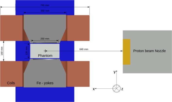
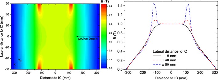
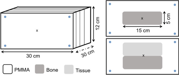
Methods: Proton beam interactions with magnetic fields were simulated using the GATE/Geant4 toolkit. The transport of charged particle in custom 3D magnetic field maps was implemented for the first time in GATE. Validation experiments were done using a horizontal proton pencil beam scanning system with energies between 62.4 and 252.7 MeV and a large gap dipole magnet (B = 0-1 T), positioned at the isocenter and creating magnetic fields transverse to the beam direction. Dose was measured with Gafchromic EBT3 films within a homogeneous PMMA phantom without and with bone and tissue equivalent material slab inserts. Linear energy transfer (LET) quenching of EBT3 films was corrected using a linear model on dose-averaged LET method to ensure a realistic dosimetric comparison between simulations and experiments. Planar dose distributions were measured with the films in two different configurations: parallel and transverse to the beam direction using single energy fields and spread-out Bragg peaks. The MC model was benchmarked against lateral deflections and spot sizes in air of single beams measured with a Lynx PT detector, as well as dose distributions using EBT3 films. Experimental and calculated dose distributions were compared to test the accuracy of the model.
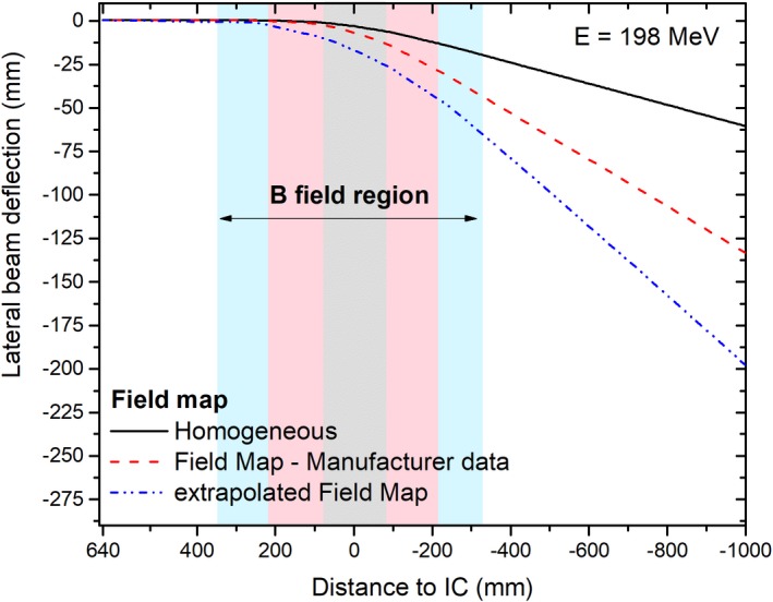
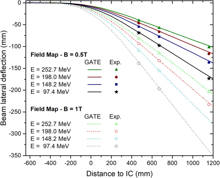
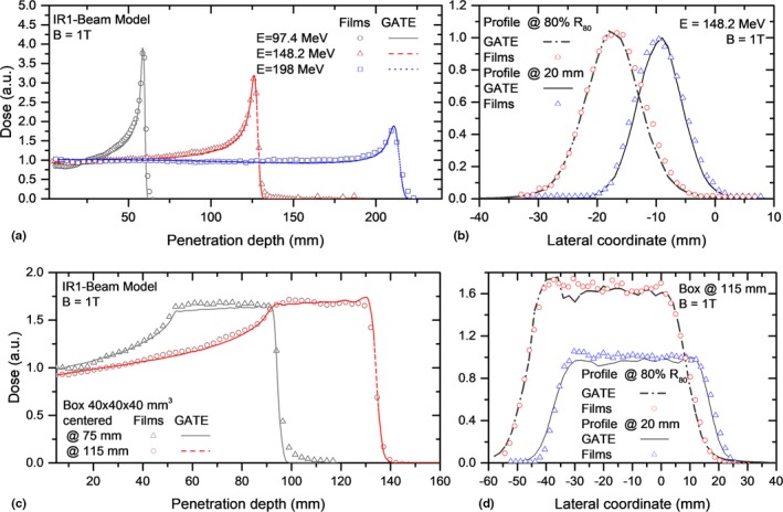
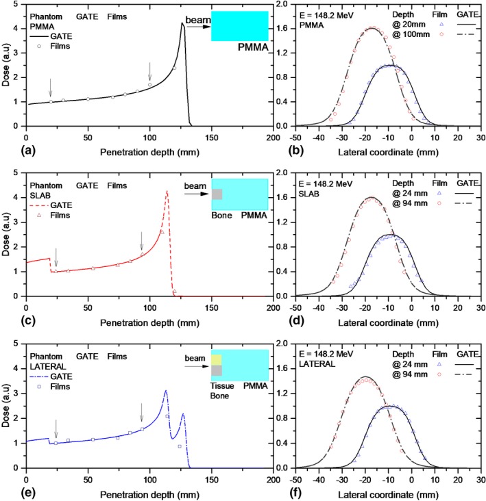
Results: Measured proton beam deflections in air at distances of 465, 665, and 1155 mm behind the isocenter after passing the magnetic field region agreed with MC-predicted values within 4 mm. Differences between calculated and measured beam full width at half maximum (FWHM) were lower than 2 mm. For the homogeneous phantom, measured and simulated in-depth dose profiles showed range and average dose differences below 0.2 mm and 1.2%, respectively. Simulated central beam positions and widths differed <1 mm to the measurements with films. For both heterogenous phantoms, differences within 1 mm between measured and simulated central beam positions and widths were obtained, confirming a good agreement of the MC model.
Conclusions: A GATE/Geant4 beam model for protons interacting with magnetic fields up to 1 T was developed and benchmarked to experimental data. For the first time, the GATE/Geant4 model was successfully validated not only for single energy beams, but for SOBP, in homogeneous and heterogeneous phantoms. EBT3 film dosimetry demonstrated to be a powerful dosimetric tool, once the film response function is LET corrected, for measurements in-line and transverse to the beam direction in magnetic fields. The proposed MC beam model is foreseen to support treatment planning and quality assurance (QA) activities toward MRPT.
Keywords: MC simulations; beam modeling; magnetic fields; proton therapy.
© 2019 The Authors. Medical Physics published by Wiley Periodicals, Inc. on behalf of American Association of Physicists in Medicine.
Conflict of interest statement
The authors have no conflict of interest to report.
Figures
References
-
- Raaymakers BW, Raaijmakers AJE, Lagendijk JJW. Feasibility of MRI guided proton therapy: magnetic field dose effects. Phys Med Biol. 2008;53:5615–5622. - PubMed
-
- Wolf R, Bortfeld T. An analytical solution to proton Bragg peak deflection in a magnetic field. Phys Med Biol. 2012;57:N329–N337. - PubMed
-
- Hartman J, Kontaxis C, Bol GH, et al. Dosimetric feasibility of intensity modulated proton therapy in a transverse magnetic field of 1.5 T. Phys Med Biol. 2015;60:5955–5969. - PubMed
-
- Oborn BM, Dowdell S, Metcalfe PE, Crozier S, Keall PJ. Future of medical physics: Real‐time MRI‐guided proton therapy. - PubMed
MeSH terms
Grants and funding
LinkOut - more resources
Full Text Sources
Other Literature Sources
Miscellaneous
