. 2019 Nov;575(7782):385-389.
doi: 10.1038/s41586-019-1723-0. Epub 2019 Oct 30.

Fundamental roles of chromatin loop extrusion in antibody class switching

Affiliations

Fundamental roles of chromatin loop extrusion in antibody class switching

Xuefei Zhang et al. Nature. 2019 Nov.

Abstract

Antibody class switch recombination (CSR) in B lymphocytes replaces immunoglobulin heavy chain locus (Igh) Cμ constant region exons (CHs) with one of six CHs lying 100-200 kb downstream1. Each CH is flanked upstream by an I promoter and long repetitive switch (S) region1. Cytokines and activators induce activation-induced cytidine deaminase (AID)2 and I-promoter transcription, with 3' IgH regulatory region (3' IgHRR) enhancers controlling the latter via I-promoter competition for long-range 3' IgHRR interactions3-8. Transcription through donor Sμ and an activated downstream acceptor S-region targets AID-generated deamination lesions at, potentially, any of hundreds of individual S-region deamination motifs9-11. General DNA repair pathways convert these lesions to double-stranded breaks (DSBs) and join an Sμ-upstream DSB-end to an acceptor S-region-downstream DSB-end for deletional CSR12. AID-initiated DSBs at targets spread across activated S regions routinely participate in such deletional CSR joining11. Here we report that chromatin loop extrusion underlies the mechanism11 by which IgH organization in cis promotes deletional CSR. In naive B cells, loop extrusion dynamically juxtaposes 3' IgHRR enhancers with the 200-kb upstream Sμ to generate a CSR centre (CSRC). In CSR-activated primary B cells, I-promoter transcription activates cohesin loading, leading to generation of dynamic subdomains that directionally align a downstream S region with Sμ for deletional CSR. During constitutive Sα CSR in CH12F3 B lymphoma cells, inversional CSR can be activated by insertion of a CTCF-binding element (CBE)-based impediment in the extrusion path. CBE insertion also inactivates upstream S-region CSR and converts adjacent downstream sequences into an ectopic S region by inhibiting and promoting their dynamic alignment with Sμ in the CSRC, respectively. Our findings suggest that, in a CSRC, dynamically impeded cohesin-mediated loop extrusion juxtaposes proper ends of AID-initiated donor and acceptor S-region DSBs for deletional CSR. Such a mechanism might also contribute to pathogenic DSB joining genome-wide.


Figures
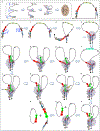
Extended Data Figure 1.
Extended Data Figure 1.. Working model for cohesin-mediated chromatin loop extrusion-driven deletional CSR joining.
a, Cohesin (blue rings) loaded at the indicated HS sites within the 3’IgHRR dynamically extrude 3’IgHRR chromatin which aligns the HS sites as transient loop anchors (brown oval). b-e, In resting B cells, cohesin is loaded (blue arrows) at either Iμ-Sμ (red rectangles) or the 3'IgHRR. While similar models could be drawn for both, we illustrate one in which loading occurs at 3'IgHRR (brown oval) and downstream extrusion is impeded by 3'IgHRR/3'CBEs chromatin to generate a dynamic impediment for extrusion of upstream chromatin that brings iEμ/Iμ/Sμ into proximity with the 3’IgHRR to generate a CSRC (Grey circle). In this process, upstream extrusion is strongly impeded at the V(D)J/iEμ locale. f, g, B cell activation primes a targeted S region promoter (light green becoming darker green, which is activated for high level transcription (bright green) after extrusion into proximity with the 3’IgHRR. h, i, Downstream extrusion of cohesin loaded at the activated S region is impeded by activated S region chromatin allowing extrusion of upstream chromatin to dynamically align targeted S region with Sμ. j-p, Activation-induced AID is transcriptionally targeted to Sμ and the activated S region leading to DSBs (lightning bolts) in one or the other and, ultimately, in both. Cohesin-mediated loop extrusion pulls S region DSB ends into cohesin rings stalling extrusion and aligning them for deletional end-joining. DSBs in the Sμ and activated S regions need not occur at the same spatial location or time in this model. See also Text and Supplementary Video 1.
Extended Data Figure 2.
Extended Data Figure 2.. Cytokine/activator-induced S region transcription promotes dynamic loop formation and S-S synapsis during CSR.
a, (left) Additional repeats of GRO-Seq profiles shown in Fig. 1c from non-stimulated and αCD40/IL4 stimulated AID−/− mature splenic B cells. (right), Zoom-in view of the GRO-Seq profiles on the left to better reveal the transcription level around the iEμ-Cδ locale from non-stimulated and αCD40/IL4-stimulated AID−/− mature splenic B cells. b, c, Additional repeats of 3C-HTGTS profiles shown in Fig. 1d, e from non-stimulated and αCD40/IL4-stimulated AID−/− mature splenic B cells using iEμ/Iμ (b) or 3’IgHRR(HS4) (c) locale as baits (blue asterisks). Bar graphs on the right of 3C-HTGTS profiling show the relative iEμ/Iμ or 3’IgHRR(HS4) interaction frequency with Sγ1 and Sε in αCD40/IL4-stimulated mature splenic B cells. Diagrams on the top of the 3C-HTGTS profiling show the digestion/bait strategies used for the 3C-HTGTS experiments. d, e, 3C-HTGTS profiles of interactions within the 3'IgH locus domain in αCD40/IL4-stimulated AID−/− mature splenic B cells using the first (d) and seventh (e) 3’CBE locale as baits (blue asterisk). Diagrams on the right of the 3C-HTGTS profiling show the digestion/bait strategies used for the 3C-HTGTS experiments. f, g, Additional repeats of NIPBL (f) and Rad21 (g) ChIP-Seq shown in Fig. 1f, g from non-stimulated and αCD40/IL4 stimulated AID−/− mature splenic B cells. Bar graphs on the right of the ChIP-Seq profiling show NIPBL and Rad21 accumulation of indicated regions. All bar graph data represent mean ± s.d. in panels b-c and f-g from three biologically independent repeats. P values were calculated via an unpaired two-tailed t-test. All other bars and symbols are as indicated in Figure 1 legend.
Extended Data Figure 3.
Extended Data Figure 3.. Iα deletion promotes CSR to upstream S regions.
a, Illustration of dominant, deletional CSR between Sμ and Sα in CH12F3 cells. b, Illustration of Cas9/gRNA targeting (lightning bolts) used to generate the CH12F3NCΔ line. c, Southern blot confirmation (using BamHI digestion and a JH4 probe) of the CH12F3NCΔ lines (done twice independently with similar results). d, Western blot confirmation of AID expression or lack of expression, respectively, in AID sufficient and deficient (via targeted deletion) CH12F3NCΔ and IαΔ lines following stimulation with αCD40/IL4/TGFβ for 72 hrs (done twice independently with similar results). e, FACS analysis for surface IgA expression in CH12F3NCΔ-AID−/− cells stimulated with αCD40/IL4/TGFβ for 72 hrs (done three times independently with similar results). f, Three repeats of CSR-HTGTS-Seq data shown in Fig. 2b for αCD40/IL4/TGFβ-stimulated CH12F3NCΔ and IαΔ cells (3 biologically independent repeats). Junctions are plotted at 2.5 kb bin size. The blue lines indicate deletional joining and the red lines indicate inversional joining. Bar graph shows percentages of junctions located in different regions from CH12F3NCΔ and IαΔ cells. Data represents mean ± s.d. from three biologically independent repeats. P values were calculated via an unpaired two-tailed t-test. g, FACS analysis of IgA, IgG3 and IgG2b surface expression in CH12F3NCΔ and IαΔ cells stimulated with αCD40/IL4/TGFβ for 72 hrs (4 biologically independent repeats). Bar graph shows percentages of IgA, IgG3 and IgG2b expression on CH12F3NCΔ and IαΔ cells. Data represents mean ± s.d. from four biologically independent repeats. P values were calculated via an unpaired two-tailed t-test.
Extended Data Figure 4.
Extended Data Figure 4.. Iα deletion promotes transcription to upstream S regions.
a, GRO-Seq profile of repeat #1 (shown immediately below it) with an enlarged scale to allow better comparison of relative transcription levels of different portions of the IgH constant region in CH12F3NCΔ-AID−/− and IαΔ-AID−/− cells with or without αCD40/IL4/TGFβ stimulation (3 biologically independent repeats with similar results). Green asterisks indicate the HS3a, HS1,2 and HS4 sites within 3’IgHRR. b, Three repeats of the GRO-Seq profiles with a smaller scale to better reveal low, but significant transcription of Cγ2b and Cγ2a (upon Iα-deletion) in CH12F3NCΔ-AID−/− and IαΔ-AID−/− cells with or without αCD40/IL4/TGFβ stimulation. c, Higher zoom-in view of the three repeats of GRO-Seq profiles to better reveal induced anti-sense transcription in the region between Sγ3 to Sε in IαΔ-AID−/− versus CH12F3NCΔ-AID−/− cells with or without αCD40/IL4/TGFβ stimulation. d, Bar graph shows GRO-Seq transcriptional activity (calculated as RPM) of the different indicated S regions in αCD40/IL4/TGFβ stimulated CH12F3NCΔ-AID−/− cells and IαΔ-AID−/− cells (3 biologically independent repeats). Bar graph panel represents mean ± s.d. from three biologically independent repeats. P values were calculated via unpaired two-tailed t-test. Grey Bars highlight the iEμ-Cμ, Iγ3-Cγ3, Iγ2b-Cγ2b, Iγ2a-Cγ2a, Iα-Cα, 3'IgHRR and 3'CBEs.
Extended Data Figure 5.
Extended Data Figure 5.. Constitutively transcribed Sα leads to constitutively synapsis of Sα with Sμ in CH12F3 cells.
a, b, Additional repeats for the 3C-HTGTS profiles shown in Fig. 2d, e, from non-stimulated and αCD40/IL4/TGFβ stimulated CH12F3NCΔ-AID−/− cells using iEμ/Iμ (a) or HS4 (b) locale as baits (blue asterisks). Green asterisks indicate the HS3a, HS1,2 and HS4 sites within 3’IgHRR. Grey Bars highlight the iEμ-Cμ, Sα, 3'IgHRR and 3'CBEs. c, d, NIPBL (c) and Rad21 (d) ChIP-Seq profiles of non-stimulated and αCD40/IL4/TGFβ stimulated CH12F3NCΔ-AID−/− cells. Green asterisks indicate the Iα, HS3a, HS1,2, HS3b, HS4 and HS7 sites that were implicated by this experiment as targets for cohesin loading. Grey Bars highlight the broader regions around Sμ, Sα, the 3'IgHRR and the 3'CBEs. e, Loop extrusion-mediated Sμ-Sα synapsis in CH12F3 cells. I, Cohesin is loaded at various Igh locations including transcriptionally activated Iα-Sα. II-IV, For cohesin loaded at Iα locale downstream extrusion is impeded by transcribed Sα allowing upstream extrusion to proceed until being dynamically impeded by transcribed iEμ-Sμ-Cμ locale resulting in Sμ and Sα being brought into proximity without complete alignment. During upstream extrusion, the activated Iα promoter blocks extrusion-mediated activation of upstream I promoters by the 3'IgHRR via promoter competition. V, VI, Continued loading of cohesin at the Iα locale is impeded for downstream extrusion allowing continued upstream extrusion until reaching the transcribed Sμ locale causing dynamic Sα/Sμ synapsis. VII-X, Activation-induced AID is transcriptionally targeted to Sμ and the activated Sα leading to DSBs (lightning bolts) in one or the other and, ultimately, in both. Cohesin-mediated loop extrusion pulls S region DSB ends into cohesin rings stalling extrusion and aligning them for deletional end-joining. This model could be explained by other variations including cohesin loading at Sμ or the 3'IgHRR or a process like that in Extended Data Fig. 1.
Extended Data Figure 6.
Extended Data Figure 6.. Iα deletion increases iEμ/Iμ and HS4 interactions across the upstream CH domain.
a, b, (left) Additional repeats for the 3C-HTGTS profiles shown in Fig. 2d, e, from αCD40/IL4/TGFβ-stimulated CH12F3NCΔ-AID−/− and IαΔ-AID−/− cells using iEμ/Iμ (a) or HS4 (b) locale as baits (blue asterisks). Green asterisks indicate 3'IgH RR HS sites in all panels. Grey Bars highlight the iEμ-Cμ, Sγ3, Sγ2b, Sγ2a, Sα, 3'IgHRR and 3'CBEs. (right), Zoom-in view of the 3C-HTGTS profiles on the left to better reveal the interaction patterns in the region from Iγ3 to Cε in αCD40/IL4/TGFβ-stimulated CH12F3NCΔ-AID−/− and IαΔ-AID−/− cells. c, (left) 3C-HTGTS profiles of interactions across the indicated domain of non-stimulated and αCD40/IL4/TGFβ-stimulated IαΔ-AID−/− cells using the iEμ/Iμ locale as bait (blue asterisks). Grey Bars highlight the iEμ-Cμ, Sγ3, Sγ2b, Sγ2a, Sα, 3'IgHRR and 3'CBEs. (right), Zoom-in view of the 3C-HTGTS profiles on the left to better reveal the interaction patterns in the region from Sγ3 to Sε in non-stimulated and αCD40/IL4/TGFβ stimulated IαΔ-AID−/− cells.
Extended Data Figure 7.
Extended Data Figure 7.. CBEs inserted upstream of Iα lead to increased inversional Sα CSR.
a, Three repeats of Rad21 ChIP-Seq profiles of CD40/IL4/TGFβ stimulated i3CBEs-AID−/−. b, c, Additional repeats of the 3C-HTGTS profiles shown in Fig. 3f, g, from CD40/IL4/TGFβ-stimulated CH12F3NCΔ-AID−/− and i3CBEs-AID−/− cells using CBE insertion (c) or iEμ/Iμ (d) locale as baits (blue asterisk). Diagram on the right of panel c 3C-HTGTS profiling shows the digestion/bait strategies used; e, Model to address increased inversional Sα CSR in CH12F3 cells with CBEs inserted upstream of Iα. I, Cohesin is loaded at various Igh locations including transcriptionally activated Iα-Sα. II-VII, For cohesin loaded at Iα locale, extrusion past the CBE impediment allows a significant subset of cells to reach step VII to generate CSRC. VIII-X, In these cells, a significant portion of continued upstream extrusion passes by the CBE impediment to yield cells in the population with configurations shown steps IX and X. XI-XIV, The cells with the configuration shown in IX will have both deletional (XIII) and inversional (XIV) joining mediated by a diffusion-related process in the absence of complete Sμ-Sα synapsis (See text for more details). Those with the configuration shown in X will join via deletion as described in Extended Data Fig. 5e. This working model could be explained by other variations as indicated for other model figures.
Extended Data Figure 8.
Extended Data Figure 8.. 3’CBEs deletion in i3CBEs cells has little effect on the Sα CSR and Sα inversional joining.
a, Representative FACS analyses for IgH class switching from IgM to IgA for CH12F3NCΔ, i3CBEs and i3CBEs-3’CBEsΔ cells stimulated with αCD40/IL4/TGFβ for 72hrs. Bar graph on right shows FACS data from six biological independent repeats plotted as mean ± s.d. P values were calculated via an unpaired two-tailed t-test. b, CSR-HTGTS-Seq of three repeats that use 5’Sμ bait for analyses of αCD40/IL4/TGFβ-stimulated CH12F3NCΔ, i3CBEs and i3CBEs-3’CBEsΔ cells. Junctions are plotted at 200 bp bin size. Blue lines indicate deletional joining and red lines indicate inversional joining. c, Schematic of Igh CH locus from iEμ to 33kb downstream of 3'CBEs. Zoom-in view on top illustrates 3’CBEs deletion in i3CBEs lines to generate i3CBEs-3’CBEΔ lines. d, Three repeats of 3C-HTGTS profiles of αCD40/IL4/TGFβ-stimulated i3CBEs-AID−/− and i3CBEs-3’CBEΔ-AID−/− cells using the CBEs insertion locale as bait (blue asterisks).
Extended Data Figure 9.
Extended Data Figure 9.. CBE-insertion in Iα-deleted CH12F3NCΔ cells impedes IgH class-switching/CSR and creates ectopic S region.
a, (upper and middle panels) Three individual repeats of CSR-HTGTS-Seq experiments shown in Fig. 4b that employ a 5’Sμ bait to assay αCD40 region /IL4/TGFβ-stimulated IαΔ and IαΔ-i3CBEs cells. Junctions are plotted at 2.5 kb bin size. (bottom panels) Zoom-in views of three repeats of data in Fig. 4c showing junctions located in the AID-targeted ectopic S region between Cγ2a and Iε in assays of IαΔ-i3CBEc cells. Junctions are plotted at 115 bp bin size. Blue lines indicate deletional joining and red lines indicate inversional joining. b, Bar graph shows percentages of junctions located in indicated AID targeted regions from IαΔ and IαΔ-i3CBEs cells. Data represents mean ± s.d. from three biologically independent repeats. P values were calculated via an unpaired two-tailed t-test based on the three repeats. c, AID targeting motif frequency analysis of 2 kb ectopic S region targeting peak and in comparably sized region just upstream and downstream of the targeting peak. d, FACS analysis of IgG3 and IgG2b surface expression in IαΔ and IαΔ-i3CBEs cells stimulated with αCD40/IL4/TGFβ for 72 hrs (6 biologically independent repeats). Bar graph shows percentages of IgG3 and IgG2b production from IαΔ and IαΔ-i3CBEs cells. Data represents mean ± s.d. from six biologically independent repeats. P values were calculated via an unpaired two-tailed t-test.
Extended Data Figure 10.
Extended Data Figure 10.. Repeats of Figure 4e-h showing CBE-insertion in Iα-deleted CH12F3Δ cells impedes upstream transcription and looping.
a, b, c, Additional repeats of Fig. 4e-h 3C-HTGTS profiles from αCD40/IL4/TGFβ-stimulated IαΔ-AID−/− and IαΔ-i3CBEs-AID−/−cells using the CBEs insertion (a) (3 biologically independent repeats), the iEμ/Iμ (b) (3 biologically independent repeats), or the 3’IgHRR(HS4) (c) (3 biologically independent repeats) locale as baits (blue asterisks). Bar graphs on the right of the 3C-HTGTS profiles show the relative iEμ/Iμ or 3’IgHRR(HS4) interaction frequency with eS and the region between Cδ to Sγ2b. Data represents mean ± s.d. in panels b-c from three biologically independent repeats. P values were calculated via paired two-tailed t-test. d, Three repeats of Fig. 4h GRO-Seq profiles with larger scale from αCD40/IL4/TGFβ stimulated IαΔ-AID−/− and IαΔ-i3CBEs-AID−/−cells. All bars and other notations as described in the legend to Fig. 4.
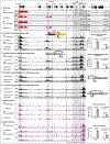
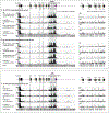
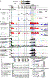
Figure 1.
Figure 1.. Cytokine -induced target S region transcription promotes synapsis with Sμ during CSR.
a, Illustration of Igh CH locus (top) and activation of CSR in normal B cells stimulated with αCD40/IL4, which induces AID and activates transcription of Iγ1(shown) and Iε (not shown). As indicated, the vast majority of CSR events are deletional, with an upstream end of an Sμ DSB joining to the downstream end of an acceptor S region DSB. b, Schematic of 3'Igh locus domain from iEμ to 3’CBEs. c, GRO-Seq profiles of AID−/− mature splenic B cells without stimulation or with αCD40/IL4 stimulation (3 biologically independent repeats with similar results). Sense transcription is shown above in red and antisense transcription is shown below in blue lines. d, e, High resolution 3C-HTGTS profiles of interactions within the 3'Igh locus domain in AID−/− mature splenic B cells without stimulation or with αCD40/IL4 stimulation as indicated using the iEμ/Iμ (d) (3 biologically independent repeats with similar results) or 3’IgHRR HS4 (e) (3 biologically independent repeats with similar results) locale as baits (blue asterisk). As portions of Sμ and certain other S regions cannot be mapped due to lack of NlaIII sites, their interactions are inferred from mappable sequences. f, g, NIPBL (f) (3 biologically independent repeats with similar results) and Rad21 (g) (3 biologically independent repeats with similar results) ChIP-Seq profiles of AID−/− mature splenic B cells without stimulation or with αCD40/IL4 stimulation as indicated. Grey Bars highlight the iEμ-Cμ, Sγ1, Sε, 3'IgHRR and 3'CBEs. Green asterisks indicate the HS3a, HS1,2 and HS4 sites within 3’IgHRR. Repeat experiments for all panels are in Extended Data Fig. 2.
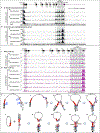
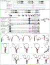
Figure 2.
Figure 2.. Constitutive CH12F3 Sα transcription causes dominant Sα CSR and impedes long-range interactions and CSR to upstream S regions.
a, Schematic of Igh CH locus from iEμ to 33kb downstream of the 3'CBEs. Zoom-in view on top illustrates deletion of Iα in CH12F3NCΔ lines to generate IαΔ lines. b, Results of CSR-HTGT-Seq analysis which measures joining of the 5' end of AID-initiated DSBs in upstream 5’ region of Sμ to either upstream (inversional) or downstream (deletional) ends of AID-initiated DSB ends in downstream acceptor S regions in CH12F3NCΔ cells and IαΔ cells stimulated with αCD40/IL4/TGFβ for 72 hrs. Junctions are plotted at 3.3 kb bin size. Blue line indicates deletional joining and red line indicates inversional joining. c, GRO-Seq profiles across the indicated Igh domain of non-stimulated CH12F3NCΔ-AID−/− cells, αCD40/IL4/TGFβ stimulated CH12F3NCΔ-AID−/− and IαΔ-AID−/− cells, other details as in Fig. 1c legend. d, e, 3C-HTGTS profiles of interactions across the indicated Igh domain of non-stimulated CH12F3NCΔ-AID−/− cells, αCD40/IL4/TGFβ stimulated CH12F3NCΔ-AID−/− and IαΔ-AID−/− cells using the iEμ/Iμ (d) or 3’IgHRR HS4 (e) locale as baits (blue asterisks). All panels in b-e were repeated three times independently and showed similar results. Grey Bars highlight the iEμ-Cμ, Sγ3, Sγ2b, Sγ2a, Sα,3'IgHRR and 3'CBEs. f. Zoom-in view 3C-HTGTS profiles in bottom two tracks of panels d and e (iEμ/Iμ and HS4 baits) to better reveal the interaction patterns in the region between Cδ to Cε in αCD40/IL4/TGFβ stimulated-CH12F3NCΔ-AID−/− and IαΔ-AID−/− cells. Bar graphs on right show the relative iEμ/Iμ or 3’IgHRR(HS4) interaction frequency with Sα and the intervening sequence between Cδ and Cε in αCD40/IL4/TGFβ stimulated CH12F3NCΔ-AID−/− and IαΔ-AID−/− cells. Data represents mean ± s.d. from three biologically independent samples. P values were calculated via an unpaired two-tailed t-test. Repeat experiments for all panels are in Extended Data Fig. 3, 4, 5, 6.
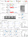
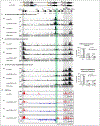
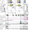
Figure 3.
Figure 3.. Inserting CBEs upstream of Iα activates inversional CH12F3 CSR.
a, Illustration of i3CBEs insertion in CH12F3NCΔ lines to generate i3CBEs lines. CBEs and their orientation are indicated by blue arrowheads. b, IgH class-switching to IgA in αCD40/IL4/TGFβ stimulated (72 hrs) in CH12F3NCΔ and i3CBEs cells (6 biologically independent repeats). Data represents mean ± s.d. from six biologically independent repeats. P values were calculated via an unpaired two-tailed t-test. c, CSR-HTGT-Seq analysis of the CH12F3NCΔ (6 biologically independent repeats with similar results) and i3CBEs (3 biologically independent repeats with similar results) cells stimulated with αCD40/IL4/TGFβ for 72 hrs. Junctions are plotted at 200 bp bin size. d, Bar graph showing the percentages of inversional end joining between 5’Sμ DSB ends and Sα DSBs in αCD40/IL4/TGFβ stimulated (72 hrs) CH12F3NCΔ (n=6 libraries) and i3CBEs cells (n=3 libraries). Data represents mean ± s.d. from biological independent samples. P values were calculated via an unpaired two-tailed t-test. e, Rad21 ChIP-Seq profiles of αCD40/IL4/TGFβ stimulated CH12F3NCΔ-AID−/− and i3CBEs-AID−/− cells (3 biologically independent repeats with similar results). Green asterisk indicates cohesin accumulation at the CBEs insertion site. f, g, 3C-HTGTS profiles of αCD40/IL4/TGFβ stimulated CH12F3NCΔ-AID−/− and i3CBEs-AID−/− cells using either the CBEs insertion (f) (3 biologically independent repeats with similar results) or iEμ/Iμ (g) (3 biologically independent repeats with similar results) locale as bait (blue asterisk). Grey Bars highlight the broader regions around the Sμ, i3CBEs, Sα, 3'IgHRR and 3'CBEs. Repeat experiments for all panels are in Extended Data Fig. 7, 8.
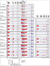
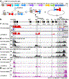
Figure 4.
Figure 4.. CBE-insertion in Iα-deleted CH12F3Δ cells impedes upstream transcription, looping and CSR and creates ectopic S region.
a, Schematic of Igh CH locus from iEμ to 3'CBEs. Zoom-in view shows i3CBEs insertion site in IαΔ lines to generate IαΔ-i3CBEs lines. b, CSR-HTGTS-Seq analysis of break joining between 5’Sμ and downstream acceptor S or non-S regions in IαΔ and IαΔ-i3CBEs cells stimulated with αCD40/IL4/TGFβ for 72 hrs (3 biological independent repeats with similar results). Junctions are plotted at 2.3 kb bin size. Blue line indicates deletional joining and red line indicates inversional joining. In the lower panel the location of the AID-targeted ectopic S region (labeled as "eS") between Cγ2a and Iα is highlighted by a transparent green bar through all panels. Grey Bars highlight the iEμ-Cμ, Sγ3, Sγ1, Sγ2b, Sγ2a, Sε, 3'IgHRR and 3'CBEs. c, Zoom-in view of CSR-HTGTS-Seq junctions located in the AID-targeted ectopic S region between Cγ2a and Iε from IαΔ-i3CBEs cells (3 biological independent repeats with similar results). Junctions are plotted at 115 bp bin size. d, AID targeting motif analysis for the junctions located in a 250bp region within AID-targeted ectopic S region from IαΔ-i3CBEs cells (3 biological independent repeats with similar results). Blue asterisks in this panel indicate DGYW motifs and red asterisks indicate AGCT motifs. e, f, g, 3C-HTGTS profiles of αCD40/IL4/TGFβ stimulated IαΔ-AID−/− and IαΔ-i3CBEs-AID−/− cells using, respectively, the CBEs insertion (e) (3 biological independent repeats with similar results), the iEμ/Iμ (f) (3 biological independent repeats with similar results), or the 3’IgHRR(HS4) (g) (3 biological independent repeats with similar results) locale as baits (bait sites denoted by blue asterisk). h, GRO-Seq analysis of αCD40/IL4/TGFβ stimulated IαΔ-AID−/− and IαΔ-i3CBEs-AID−/− cells (3 biological independent repeats with similar results). Repeat experiments for all panels are in Extended Data Fig. 9, 10.

Comment in

  • One ring to rule them all.
    Livak F, Nussenzweig A. Livak F, et al. Nature. 2019 Nov;575(7782):291-293. doi: 10.1038/d41586-019-03200-4. Nature. 2019. PMID: 31719691 No abstract available.

References

    1. Matthews AJ, Zheng S, DiMenna LJ & Chaudhuri J Regulation of immunoglobulin class-switch recombination: choreography of noncoding transcription, targeted DNA deamination, and long-range DNA repair. Adv Immunol 122, 1–57, doi:10.1016/B978-0-12-800267-4.00001-8 (2014). - DOI - PMC - PubMed
    1. Muramatsu M et al. Class switch recombination and hypermutation require activation-induced cytidine deaminase (AID), a potential RNA editing enzyme. Cell 102, 553–563 (2000). - PubMed
    1. Cogne M et al. A class switch control region at the 3’ end of the immunoglobulin heavy chain locus. Cell 77, 737–747 (1994). - PubMed
    1. Manis JP et al. Class switching in B cells lacking 3’ immunoglobulin heavy chain enhancers. J Exp Med 188, 1421–1431 (1998). - PMC - PubMed
    1. Seidl KJ et al. Position-dependent inhibition of class-switch recombination by PGK-neor cassettes inserted into the immunoglobulin heavy chain constant region locus. Proc Natl Acad Sci U S A 96, 3000–3005 (1999). - PMC - PubMed

Publication types