Review
. 2019 Jul 22;3(11):1900050.
doi: 10.1002/gch2.201900050. eCollection 2019 Nov.

Potential Substitutes for Replacement of Lead in Perovskite Solar Cells: A Review

Affiliations
Review

Potential Substitutes for Replacement of Lead in Perovskite Solar Cells: A Review

Ravinder Kour et al. Glob Chall. .

Abstract

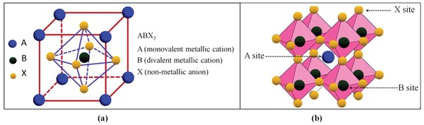
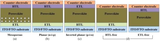
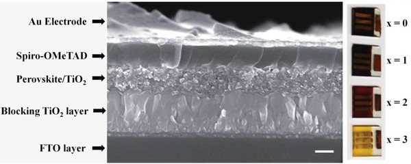
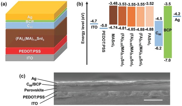
Lead halide perovskites have displayed the highest solar power conversion efficiencies of 23% but the toxicity issues of these materials need to be addressed. Lead-free perovskites have emerged as viable candidates for potential use as light harvesters to ensure clean and green photovoltaic technology. The substitution of lead by Sn, Ge, Bi, Sb, Cu and other potential candidates have reported efficiencies of up to 9%, but there is still a dire need to enhance their efficiencies and stability within the air. A comprehensive review is given on potential substitutes for lead-free perovskites and their characteristic features like energy bandgaps and optical absorption as well as photovoltaic parameters like open-circuit voltage (V OC), fill factor, short-circuit current density (J SC), and the device architecture for their efficient use. Lead-free perovskites do possess a suitable bandgap but have low efficiency. The use of additives has a significant effect on their efficiency and stability. The incorporation of cations like diethylammonium, phenylethyl ammonium, phenylethyl ammonium iodide, etc., or mixed cations at different compositions at the A-site is reported with engineered bandgaps having significant efficiency and stability. Recent work on the advancement of lead-free perovskites is also reviewed.

Keywords: lead‐free perovskites; photovoltaic parameters; stability.


Conflict of interest statement

The authors declare no conflict of interest.

Figures

Figure 1
Figure 1
a) Schematic view of cubic perovskite crystal structure for ABX3 compound, b) 3D crystal structure in which the A site is confined within a cage determined by the octahedral coordination of B site with X site. Reproduced with permission.1 Copyright 2019, Royal Society of Chemistry.
Figure 2
Figure 2
a) Device structure of mesoporous PSCs, b) planar heterojunction, c) inverted planar PCSs, and d) HTM‐free PSCs. Reproduced with permission.66 Copyright 2016, Springer Nature.
Figure 3
Figure 3
SEM image of a photovoltaic device using CH3NH3SnI3 perovskite material. Reproduced with permission.106 Copyright 2014, Springer Nature.
Figure 4
Figure 4
a) Schematic device structure of (FA)x(MA)1− xSnI3 perovskite solar cell. b) Band alignment diagram. c) Cross‐sectional scanning electron microscope (SEM) image of a completed device (scale bar: 500 nm). Reproduced with permission.150 Copyright 2017, Wiley‐VCH.
Figure 5
Figure 5
A) Scheme of the “inverted” structure planar B‐γ‐CsSnI3 PSC device employing NiOx as HTL and PCBM as ETL, and B) corresponding energy level diagram (the dashed line indicates NiOx work function). Reproduced with permission.157 Copyright 2016, Wiley‐VCH.
Figure 6
Figure 6
a) Schematic of the device architecture used in this work; b) SEM image of a CsSnI3 film prepared with a 10 mol% excess SnI2 and spin cast at 4000 rpm from 8 wt% solution onto an ITO glass substrate coated with a 100 nm layer of CuI. Reproduced with permission.159 Copyright 2015, Royal Society of Chemistry.
Figure 7
Figure 7
SEM images. a) Top view of a film of CH3NH3SnI3 spin‐coated onto mesoporous TiO2 (80 nm thickness). b) Top view of a spin‐coated film of CH3NH3PbI3− xClx on mesoporous TiO2 (400 nm thickness). c) Top view of a spin‐coated film of CH3NH3SnI3 on mesoporous TiO2 (400 nm thickness). d) Cross‐sectional view of a complete device active layer composed of FTO glass/compact TiO2 (50 nm)/mesoporous TiO2 infiltrated with CH3NH3SnI3 (400 nm)/Spiro‐OMeTAD (600 nm). Reproduced with permission.120 Copyright 2014, Royal Society of Chemistry.
Figure 8
Figure 8
Schematic energy‐level diagram of CH3NH3SnI3− xBrx compounds. Reproduced with permission.106 Copyright 2014, Springer Nature.
Figure 9
Figure 9
a) Configuration of the FASnI2Br‐based p‐i‐n heterojunction solar cells and its cross‐sectional SEM image of a typical device. Reproduced with permission.171 Copyright 2016, Springer Nature. b) Cross‐sectional SEM image of the entire device with 10 mol% SnF2 additives, in which each layer is labeled, and schematic of energy level diagram of our FASnI3 perovskite solar cells. Reproduced with permission.172 Copyright 2016, Wiley‐VCH.
Figure 10
Figure 10
Top and cross‐sectional SEM view of MBI perovskite layer deposited on a,b) TiO2 compact layer and c,d) brookite mesoporous layer. Reproduced with permission.174 Copyright 2016, American Chemical Society.
Figure 11
Figure 11
a) Schematic representations of perovskite crystals in the presence of BAI and EDAI2 additives; top‐view SEM images of b) pristine FASnI3, c) FASnI3‐BAI 15%, and d) FASnI3‐EDAI2 1%; e) current–voltage curves, f) corresponding IPCE spectra with integrated current densities, g) histograms of 30 fresh cells fabricated under the same experimental conditions, h) Mott–Schottky plots, i) Nyquist plots obtained from electrochemical impedance spectra (EIS), and j) stabilized power‐conversion efficiencies and photocurrent densities of the FASnI3‐BAI 15%and FASnI3‐EDAI2 1% devices for 240 s; Reproduced with permission.203 Copyright 2018, Royal Society of Chemistry. k) Device structure, l) JV curves, m) EQE curves, and n) PCE statistics of the FASnI3 solar cells with and without 10% PN and 10% TN; Reproduced with permission.206 Copyright 2018, American Chemical Society.
Figure 12
Figure 12
a) Schematic diagram for development of evaporation‐assisted solution (EAS) method using CsSnI3. b) JV curves of the device by EAS method in both forward and reverse directions, c) IPCE spectrum of the optimized device (V oc = 0.265 V, J sc = 15.25 mA cm−2, FF = 46.05%, and PCE = 1.86%), d) steady‐state current density of champion device at a bias of 0.18 V, and d) PCE histogram of 25 tested devices. Reproduced with permission.170 Copyright 2018, Wiley‐VCH.
Figure 13
Figure 13
Schematic diagram for the unit cell of a) CsGeI3 and b) MAGeI3; Reproduced with permission.229 Copyright 2015, American Chemical Society. c) Optical absorption spectrum of CsGeI3, MAGeI3, and FAGeI3, in comparison with CsSnI3. d) Calculated band structure and projected density of states of CsGeI3. The energy of the highest occupied state is set to 0 eV. e) Photoelectron spectroscopy in air (PESA) of powder samples and f) schematic energy level diagram of CsGeI3, MAGeI3, and FAGeI3; Reproduced with permission.144 Copyright 2012, Royal Society of Chemistry.
Figure 14
Figure 14
SEM images of (MA)3Bi2I9 without and with different concentration of NMP additives. Reproduced with permission.244 Copyright 2017, Royal Society of Chemistry.
Figure 15
Figure 15
Schematic of the device configuration used for switchable photovoltaic study using (NH4)3(Sb(1− x )Bix)2I9 perovskite material. Reproduced with permission.275 Copyright 2018, Wiley‐VCH.
Figure 16
Figure 16
Chemical structures of perovskite solar cells using a) (CH3NH3)2CuCl4, b) (CH3NH3)2CuCl2I2, and c) (CH3NH3)2CuCl2Br2 powders. d) Current–voltage curve and e) EQE spectra of solar cells. Reproduced with permission.277 Copyright 2018, American Chemical Society.
Figure 17
Figure 17
a,b) Atomic structures of CH3NH3PbI3 and CH3NH3BiSeI2 and a schematic illustrating the split‐anion approach to replacing Pb in CH3NH3PbI3. c,d) The calculated bandgaps of CH3NH3PbI3 and CH3NH3BiSeI2, respectively, using improved methods from PBE, HSE to HSE+SOC. The alignment of the band edge positions was obtained by assuming that the reference potentials from different methods are the same. Reproduced with permission.295 Copyright 2016, Royal Society of Chemistry.
Figure 18
Figure 18
Light absorption spectrum of pristine and metal‐doped (Ni, Mn) CsGeI3 perovskite as a function of a) photon energy dependent absorption coefficient, b) wavelength‐dependent absorption coefficient, c) reflectivity, d) conductivity, e) dielectric constant (real part), and f) dielectric constant (imaginary part). Reproduced with permission.305 Copyright 2018, Royal Society of Chemistry.

References

    1. Tanaka H., Misono M., Curr. Opin. Solid State Mater. Sci. 2001, 5, 381.
    1. Yi Z., Ladi N. H., Shai X., Li H., Shen Y., Wang M., Nanoscale Adv. 2019, 1, 1276. - PMC - PubMed
    1. He T., Huang Q., Ramirez A., Wang Y., Regan K., Rogado N., Hayward M. A., Haas M. K., Slusky J. S., Inumara K., Zandbergen H. W., Ong N. P., Cava R. J., Nature 2001, 411, 54. - PubMed
    1. Goldschmidt V. M., Die Naturwiss. 1926, 14, 477.
    1. Liu X., Hong R., Tian C., J. Mater. Sci.: Mater. Electron. 2009, 20, 323.

LinkOut - more resources