Review
. 2020 Jan;9(1):e1901287.
doi: 10.1002/adhm.201901287. Epub 2019 Nov 8.

Electrospinning Piezoelectric Fibers for Biocompatible Devices

Affiliations
Review

Electrospinning Piezoelectric Fibers for Biocompatible Devices

Bahareh Azimi et al. Adv Healthc Mater. 2020 Jan.

Abstract

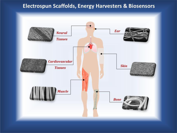
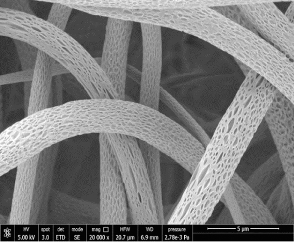
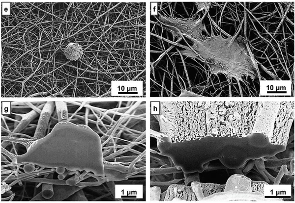
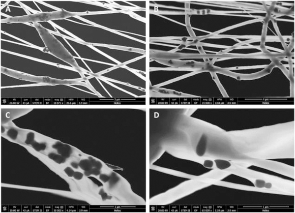
The field of nanotechnology has been gaining great success due to its potential in developing new generations of nanoscale materials with unprecedented properties and enhanced biological responses. This is particularly exciting using nanofibers, as their mechanical and topographic characteristics can approach those found in naturally occurring biological materials. Electrospinning is a key technique to manufacture ultrafine fibers and fiber meshes with multifunctional features, such as piezoelectricity, to be available on a smaller length scale, thus comparable to subcellular scale, which makes their use increasingly appealing for biomedical applications. These include biocompatible fiber-based devices as smart scaffolds, biosensors, energy harvesters, and nanogenerators for the human body. This paper provides a comprehensive review of current studies focused on the fabrication of ultrafine polymeric and ceramic piezoelectric fibers specifically designed for, or with the potential to be translated toward, biomedical applications. It provides an applicative and technical overview of the biocompatible piezoelectric fibers, with actual and potential applications, an understanding of the electrospinning process, and the properties of nanostructured fibrous materials, including the available modeling approaches. Ultimately, this review aims at enabling a future vision on the impact of these nanomaterials as stimuli-responsive devices in the human body.

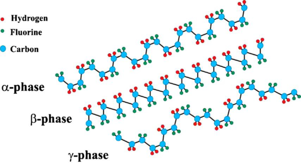
Keywords: biomaterials; biosensors; lead-free ceramics; modeling; poly(vinylidene fluoride).


Figures

Figure 1.
Figure 1.
Schematic depicting the topics covered in this review article: piezoelectric materials (ceramics and polymers) processed via electrospinning to produce piezoelectric nanofibers specific for different human body-related applications. Computational and mathematical modeling, ranging from atomistic to macroscale, represent very useful tools to tune the several parameters involved in the electrospinning of piezoelectric materials by modeling the electrospinning process, as well as the mechanical and electrical properties of the produced piezoelectric fibers and fiber meshes, thus greatly helping in reducing the experimental campaigns to achieve the desired goal.
Figure 2.
Figure 2.
Current studies on biomedical applications of electrospun tissue engineering scaffolds, energy harvesters and biosensors based on piezoelectric polymer fibers produced via electrospinning. Electrically responsive tissues targeted by researches are neural (brain), sensorineural (inner ear), cardiovascular (heart), skin (epidermis), musculoskeletal (striated muscle and bone). The piezoelectric fibrous materials serve for mechanical support and electrical stimulation of biological tissues and smart devices.
Figure 3.
Figure 3.
SEM micrograph of nanoporous surface of P(VDF-TrFE) electrospun ultrafine fibers obtained by using MEK as a solvent and > 40% humidity. Unpublished original picture by the authors.
Figure 4.
Figure 4.
Saos-2 cells cultured on PVDF electrospun samples: (e, f ) hydrophobic and hydrophilic PVDF electrospun scaffolds, respectively; (g, h) SEM-FIB cross-sections of Saos-2 cells grown on hydrophobic and hydrophilic electrospun scaffolds, respectively. Adapted with permission.[59] Copyright 2019, The Royal Society of Chemistry.
Figure 5.
Figure 5.
STEM micrographs of BTNP/PVDF 10/90 electrospun fibers obtained with a collector tangential velocity of 3.7m·s−1 at different magnifications in the range of 10,000x to 65,000x. (A, B) dispersion of BTNPs inside the electrospun fibers; (A) beads induced by the presence of BTNP aggregates; (C) BTNP aggregates inside an electrospun fiber; and (D) BTNP dispersed inside an electrospun fiber. Reproduced with permission. [69] Copyright 2017, Elsevier.
Figure 6.
Figure 6.
Confocal fluorescence microscopy images of human skin fibroblasts attached to P(VDF-TrFE) fibers after 1 and 7 days of cell culture (40x objective; cytoskeleton, green; nucleus, blue; scale bar 50 μm). Reproduced with permission. [75] Copyright 2010, Elsevier.
Figure 7.
Figure 7.
Performance of the highly flexible self-powered sensing elements (SSE) to detect skin movement. Picture of the SSE on face skin (a). (b) Output voltage and (c) current generation of the sensors induced by one eye blinking. Adapted with permission. [117] Copyright 2015, Elsevier.
Figure 8.
Figure 8.
The concept of a bendable piezoelectric sensor. Reproduced with permission. [103] Copyright 2016, American Chemical Society.
Figure 9.
Figure 9.
Electrospinning process for P(VDF–TrFE) and P(VDF–TrFE)/ZnO nanocomposites on the SAW device. Reproduced with permission under the terms of the Creative Commons Attribution 4.0 International License. [108]. Copyright 2019, Published by Springer.
Figure 10.
Figure 10.
Schematic of cell-dependent energy harvester including piezoelectric fiber mat applied on heart tissue. Reproduced with permission under the terms of the Creative Commons Attribution 4.0 International License. [126]. Copyright 2019, Published by IOP Publishing.
Figure 11.
Figure 11.
Pictures from SEM of A) a coil and J) a twisted construct made of aligned nanofibers. Reproduced with permission. [128] Copyright 2015. American Chemical Society
Figure 12.
Figure 12.
(A) SEM image of BaTiO3–PVP composite fibers prepared by electrospinning. (B) SEM image of the BaTiO3 nanofibers after Calcination in air at 700 °C for 3 h. The scale bars in the insets are 250 nm. Reproduced with permission. [151] Copyright 2006, Elsevier.
Figure 13.
Figure 13.
Rotating mandrel set-up for the electrospinning of aligned nanofibers showing the as-spun amorphous fibers aligned across the parallel copper wires on the rotating mandrel. Reproduced with permission. [156] Copyright 2016, The American Ceramic Society.
Figure 14.
Figure 14.
TEM images and NBD pattern of a single BaTiO3 nanofiber with Ce/Ba atomic ratio of 0.6%: (a) low magnification; (b) high-resolution TEM image of the red disk of (a); (c) NBD pattern of the red disk of (a). Reproduced with permission. [121]. Copyright 2015, The Royal Society of Chemistry.
Figure 15.
Figure 15.
Schematic diagram of the fabrication process of wool keratin-based Nano-generators with ferroelectric nanofibers. Reproduced with permission. [180] Copyright 2016, The Royal Society of Chemistry.
Figure 16.
Figure 16.
SEM image of a uniaxially aligned array of TiO2 hollow fibers. Reproduced with permission. [191]. Copyright 2004, American Chemical Society.
Figure 17.
Figure 17.
SEM images of (A) V2O5-TiO2-Ta2O5 nanofibers. Reproduced with permission. [192] Copyright 2006, American Chemical Society.
Figure 18.
Figure 18.
SEM images of (A) high magnification ZnO/ TiO2 heterojunctions with ZnO nanorods grown on TiO2 fibers, (B) high magnification ZnO/TiO2 heterojunctions with ZnO nanoplates grown on TiO2 fibers. Reproduced with permission. [193] Copyright 2008, The Royal Society of Chemistry.
Figure 19.
Figure 19.
Representation of the chain conformation for the α, β, and γ phases of PVDF. Adapted with permission. [207]. Copyright 2014, Elsevier.
Figure 20.
Figure 20.
Variation in morphology of electrospun nanofibers with viscosity.
Figure 21.
Figure 21.
FE-SEM images of PVDF nanofiber membranes with different types of salt: (a) no salt (pure PVDF), (b) 0.10 mol L−1 TBAC, (c) 0.10 mol L−1 TBAB, (d) 0.10 mol L−1 TEAC, (e) 0.10 mol L−1 LiCl, (f) 0.05 mol L−1 AlCl3, (g) 0.05mol L−1 CaCl2. Spinning parameter: applied voltage of 30 kV, tip to collector distance of 15 cm, extrusion rate of 1 mL h−1. Reproduced with permission. [239] Copyright 2016, Elsevier.
Figure 22.
Figure 22.
Mean fiber diameter as a function of applied voltage. The graph representation was performed according to the values found in literature.
Figure 23.
Figure 23.
Centrifugal electrospinning (CE) system for large-area production of aligned polymer nanofibers. (a) Schematic illustration of the system configuration. (b) Photograph of the CE system with deposited PVDF nanofibers. (c) Electrospun PVDF fibers deposited. Reproduced with permission. [225] Copyright 2012, The Royal Society of Chemistry.
Figure 24.
Figure 24.
A picture showing the fanning of the electrospun PVDF fibers on the modified rotating disk collector. No substrates were placed between the two aluminum electrodes. Reproduced with permission. [227] Copyright 2008, Elsevier.
Figure 25.
Figure 25.
A primitive cell of BaTiO3 where Barium, Titanium and Oxygen atoms are displayed in white, green and red respectively. Primitive cells can be employed to develop ab initio studies. Reproduced from the open database [285].
Figure 26.
Figure 26.
Model of a single electrospun fiber. The boundary conditions (BC) are the following: mechanically, the structure has the two ends fixed to the frame while, from the electric point of view, an input voltage Vin is applied only to one end (the other one is grounded). Due to the BC, a transversal displacement is observed with the highest value Δ at the middle of the fiber.
Figure 27.
Figure 27.
Investigation on the sensitivity of the output voltage V0,c with respect to the variation of the ellipsoidal axes of the cross section of the piezoelectric fiber, by taking into account the circular section as baseline. Reproduced with permission under the terms of the Creative Commons Attribution 4.0 International License. [297] Copyright 2019, Published by WILEY-VCH.
Figure 28.
Figure 28.
Investigation on the enhancement of the piezoelectric effect, in terms of output voltage Vout increment ratio with respect to the increasing number of fibers of two different cross sections (squared – black squares and circular- red circles). Case of horizontal (a) and vertical (b) packing. Reproduced with permission under the terms of the Creative Commons Attribution 4.0 International License. [297] Copyright 2019, Published by WILEY-VCH.

References

    1. Srinivasan A, Advances in polymer materials and technology. CRC Press; 2016.
    1. Kázmierski TJ, Beeby S, Energy harvesting systems: Principles, modeling and applications; 2011.
    1. Haertling GH, Journal of the American Ceramic Society 1999.
    1. Kim TH, Thesis of Master 2015, 29.
    1. Aksel E, Jones JL, Sensors 2010, 10, 1935. - PMC - PubMed

Publication types

LinkOut - more resources