. 2020 Jan:85:102746.
doi: 10.1016/j.dnarep.2019.102746. Epub 2019 Nov 6.

A combined structural and biochemical approach reveals translocation and stalling of UvrB on the DNA lesion as a mechanism of damage verification in bacterial nucleotide excision repair

Affiliations

A combined structural and biochemical approach reveals translocation and stalling of UvrB on the DNA lesion as a mechanism of damage verification in bacterial nucleotide excision repair

Marcin Jaciuk et al. DNA Repair (Amst). 2020 Jan.

Abstract

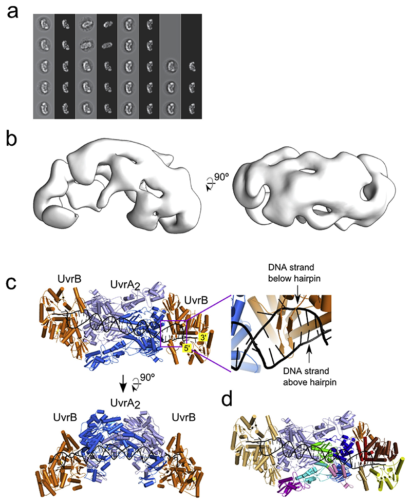
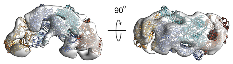
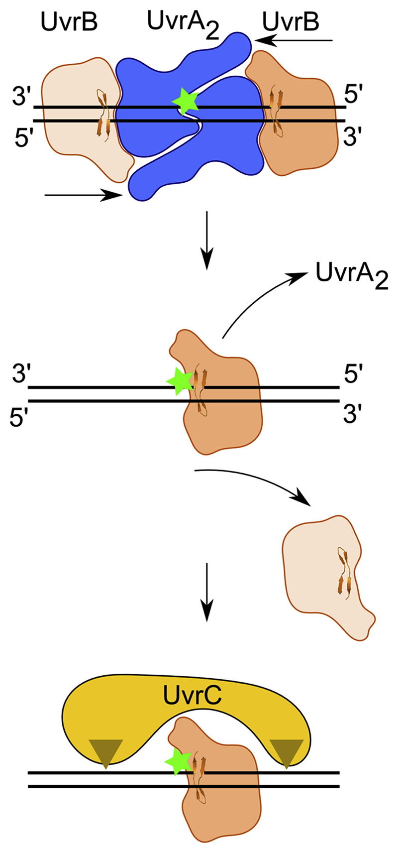
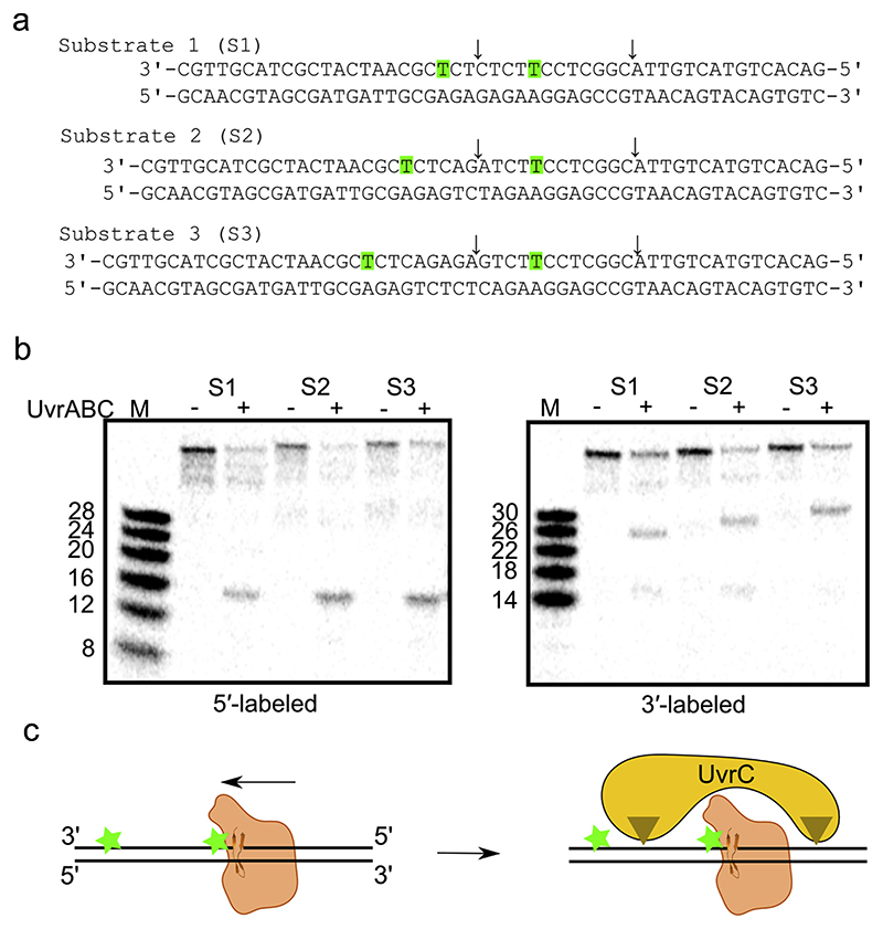
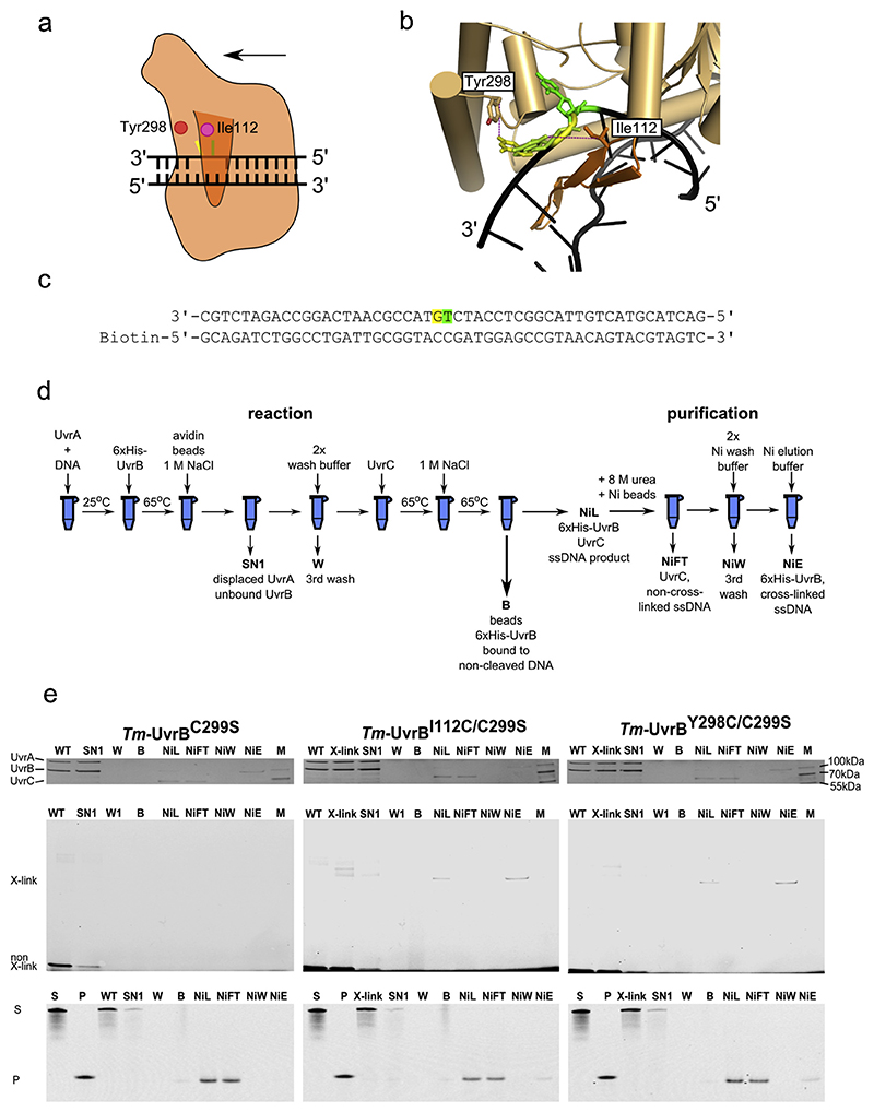
Nucleotide excision repair (NER) is a DNA repair pathway present in all domains of life. In bacteria, UvrA protein localizes the DNA lesion, followed by verification by UvrB helicase and excision by UvrC double nuclease. UvrA senses deformations and flexibility of the DNA duplex without precisely localizing the lesion in the damaged strand, an element essential for proper NER. Using a combination of techniques, we elucidate the mechanism of the damage verification step in bacterial NER. UvrA dimer recruits two UvrB molecules to its two sides. Each of the two UvrB molecules clamps a different DNA strand using its β-hairpin element. Both UvrB molecules then translocate to the lesion, and UvrA dissociates. The UvrB molecule that clamps the damaged strand gets stalled at the lesion to recruit UvrC. This mechanism allows UvrB to verify the DNA damage and identify its precise location triggering subsequent steps in the NER pathway.

Keywords: DNA repair; Prokaryotic nucleotide excision repair; UvrA; UvrB; UvrC.


Figures

Fig. 1
Fig. 1. Single-particle negative-stain electron microscopy reveals the UvrA—UvrB—DNA complex structure.
(a) Match between reference-free 2D class averages (gray back-ground) and forward-projections of the 3D structure. (b) Surface rendering of the negative-stained electron microscopy structure refined to 25.5 Å resolution. (c) Model of UvrA2—UvrB2—DNA complex (orthogonal views). UvrA dimer shown in two shades of blue. UvrB shown in orange. DNA shown in black. The inset shows a close-up view of the β-hairpin in the UvrB structure that clamps one strand of modeled DNA (based on PDB ID 2FDC) [18]. (d) Structural model colored according to protein domains. One entire UvrA subunit and one UvrB subunit are in pale blue and pale orange, respectively, while the other subunits are colored. UvrA, green − ATP-binding I, cyan − signature I, marine − ATP-binding II, blue − signature II, purple − UvrB-binding, pink − insertion domain. UvrB, brown − 1a, red − 1b, orange − 2, yellow − 3, sand − 4.
Fig. 2
Fig. 2. Fit of the theoretical model of UvrA2—UvrB2—DNA complex to an independently obtained EM map (two views).
Fig. 3
Fig. 3. Model of bacterial NER. The UvrA dimer bound at the site of DNA modification recruits two UvrB molecules.
Each UvrB molecule clamps a different DNA strand under the β-hairpin element (upper panel). Both UvrB molecules then translocate toward the lesion with 5′ to 3′ polarity on the strand under the hairpin. The UvrB molecule that clamps the modified strand will stall at the lesion (green star indicates the site of DNA modification) and the other UvrB molecule (light orange) will dissociate (middle panel). The stalled UvrB recruits UvrC double nuclease (shown in yellow), which makes two incisions indicated with triangles. Note: the top strand is shown in a 3′ to 5′ direction to match the representation of the UvrA2—UvrB2—DNA model in previous figures.
Fig. 4
Fig. 4. Incision assay with doubly modified DNA oligonucleotide.
(a) The DNA substrates used in this experiment. The residue bases in green are modified with fluorescein. Sites of observed cuts indicated with arrows. Note: the sequence of the modified strand is shown in a 3′ to 5′ direction to match the orientation in Fig. 3. (b) Incision of substrates shown in (a) by reconstituted bacterial NER machinery (T. maritima UvrA, UvrB, and UvrC). Radiolabeled substrate at the 5′ terminus or 3′ terminus. Note: 3′-labeled products migrate more slowly than expected due to the presence of the second modified thymine (see Materials and Methods). Experiment replicated four times. (c) Schematic of the experiment (colors as in Fig. 3).
Fig. 5
Fig. 5. Chemical cross-linking.
(a) Schematic of the cross-linking strategy for UvrB—DNA complex structure. Thiol-modified base shown in yellow. Fluorescein-modified base shown in green. β-hairpin shown in darker orange. The positions of the two residues (Ile112 and Tyr298) near the flipped bases indicated with circles. The direction of UvrB translocation on DNA shown with an arrow. (b) Close-up view of the hairpin region of UvrB in the UvrA2—UvrB2—DNA model. The β-hairpin element shown in a darker shade of orange. The thiol-modified base shown in yellow. The base rotated around the glycosidic bond shown in yellow-green. The fluorescein-modified base shown in green. Cross-linking distances shown as dashed lines. (c) Sequence of the DNA substrate (DNAFC) used in cross-linking experiments. Fluorescein-modified nucleotide shown in green. Thiol-modified nucleotide shown in yellow. Note: the sequence of the modified strand shown in a 3′ to 5′ direction to match the orientation in the images of the model. (d) Schematic of the experimental setup (see text and Supplementary Figures S7 and S8 for more details). ATP concentration in the experiment was 1 mM. (e) Selected fractions on silver-stained SDS-PAGE (upper panel). Selected fractions on SDS-PAGE scanned for fluorescent signals (middle panel). Analysis of selected fractions from the experiments with TBE-urea gels scanned for fluorescence (lower panel). Bands marked as X-link and non X-link represent cross-linked DNA and non-cross-linked DNA, respectively. UvrB variants used in each reaction indicated above the panels. SN1, supernatant from biotin beads; W, last wash of biotin beads; B, biotin beads boiled in sample buffer; NiL, sample loaded onto Nickel beads; NiFT, flow-through from the nickel beads; NiW, last wash of nickel beads; NiE, elution from nickel beads; M, Marker. Additional lanes on TBE-urea PAGE are S, marker for substrate; P, marker for the reaction product (12-mer DNA with fluorescein in the middle). Experiment replicated three times.

References

    1. Sancar A, Reardon JT. Nucleotide excision repair in E. Coli and man. Adv Protein Chem. 2004;69:43–71. - PubMed
    1. Truglio JJ, Croteau DL, Van Houten B, Kisker C. Prokaryotic nucleotide excision repair: the UvrABC system. Chem Rev. 2006;106:233–252. - PubMed
    1. Mellon I, Hanawalt PC. Induction of the Escherichia coli lactose operon selectively increases repair of its transcribed DNA strand. Nature. 1989;342:95–98. - PubMed
    1. Boyce RP, Howard-Flanders P. Release of ultraviolet light-induced thymine dimers from DNA in E. Coli K-12. Proc Natl Acad Sci U S A. 1964;51:293–300. doi: 10.1073/pnas.51.2.293. - DOI - PMC - PubMed
    1. Howard-Flanders P, Boyce RP, Theriot L. Three loci in Escherichia coli K-12 that control the excision of pyrimidine dimers and certain other mutagen products from DNA. Genetics. 1966;53:1119–1136. doi: 10.1093/genetics/53.6.1119. - DOI - PMC - PubMed

Publication types