

Mixing Performance of a Cost-effective Split-and-Recombine 3D Micromixer Fabricated by Xurographic Method
- PMID: 31744080
- PMCID: PMC6915444
- DOI: 10.3390/mi10110786
Mixing Performance of a Cost-effective Split-and-Recombine 3D Micromixer Fabricated by Xurographic Method
Abstract
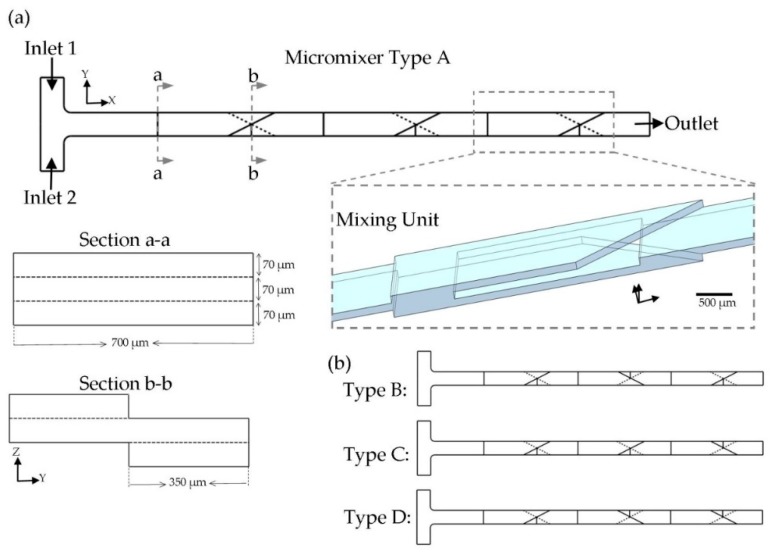
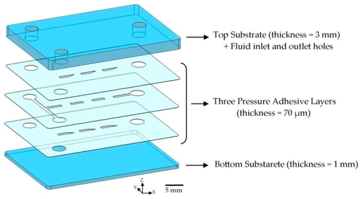
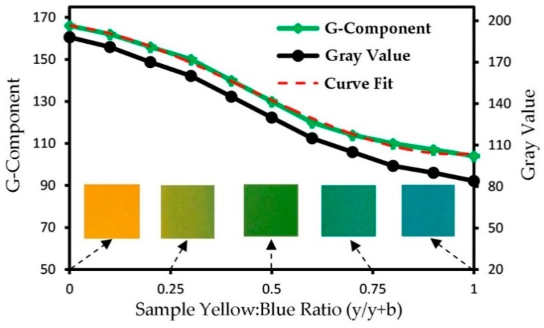
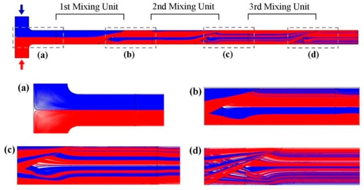
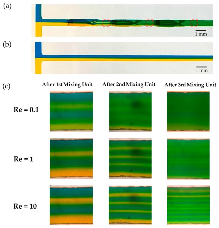
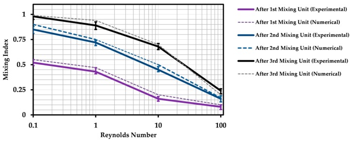
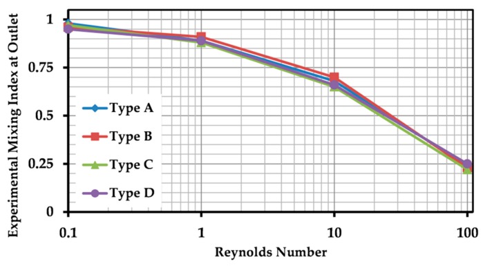
This paper presents experimental and numerical investigations of a novel passive micromixer based on the lamination of fluid layers. Lamination-based mixers benefit from increasing the contact surface between two fluid phases by enhancing molecular diffusion to achieve a faster mixing. Novel three-dimensional split and recombine (SAR) structures are proposed to generate fluid laminations. Numerical simulations were conducted to model the mixer performance. Furthermore, experiments were conducted using dyes to observe fluid laminations and evaluate the proposed mixer's characteristics. Mixing quality was experimentally obtained by means of image-based mixing index (MI) measurement. The multi-layer device was fabricated utilizing the Xurography method, which is a simple and low-cost method to fabricate 3D microfluidic devices. Mixing indexes of 96% and 90% were obtained at Reynolds numbers of 0.1 and 1, respectively. Moreover, the device had an MI value of 67% at a Reynolds number of 10 (flow rate of 116 µL/min for each inlet). The proposed micromixer, with its novel design and fabrication method, is expected to benefit a wide range of lab-on-a-chip applications, due to its high efficiency, low cost, high throughput and ease of fabrication.
Keywords: Reynolds number; diffusion; lamination; microfabrication; microfluidics; micromixer; split and recombine.
Conflict of interest statement
The authors declare no conflict of interest.
Figures

Similar articles
-
Design of passive mixers utilizing microfluidic self-circulation in the mixing chamber.Lab Chip. 2004 Feb;4(1):70-7. doi: 10.1039/b310848c. Epub 2003 Dec 4. Lab Chip. 2004. PMID: 15007444
-
An easily fabricated three-dimensional threaded lemniscate-shaped micromixer for a wide range of flow rates.Biomicrofluidics. 2017 Jan 30;11(1):014108. doi: 10.1063/1.4974904. eCollection 2017 Jan. Biomicrofluidics. 2017. PMID: 28798843 Free PMC article.
-
Xurography as a Rapid Fabrication Alternative for Point-of-Care Devices: Assessment of Passive Micromixers.Sensors (Basel). 2016 May 16;16(5):705. doi: 10.3390/s16050705. Sensors (Basel). 2016. PMID: 27196904 Free PMC article.
-
A Review of Pressure Drop and Mixing Characteristics in Passive Mixers Involving Miscible Liquids.Micromachines (Basel). 2024 May 24;15(6):691. doi: 10.3390/mi15060691. Micromachines (Basel). 2024. PMID: 38930661 Free PMC article. Review.
-
A Review of Passive Micromixers with a Comparative Analysis.Micromachines (Basel). 2020 Apr 27;11(5):455. doi: 10.3390/mi11050455. Micromachines (Basel). 2020. PMID: 32349452 Free PMC article. Review.
Cited by
-
The Influence of the Unit Junction on the Performance of a Repetitive Structure Micromixer.Micromachines (Basel). 2022 Feb 27;13(3):384. doi: 10.3390/mi13030384. Micromachines (Basel). 2022. PMID: 35334676 Free PMC article.
-
PDMS Nano-Modified Scaffolds for Improvement of Stem Cells Proliferation and Differentiation in Microfluidic Platform.Nanomaterials (Basel). 2020 Apr 2;10(4):668. doi: 10.3390/nano10040668. Nanomaterials (Basel). 2020. PMID: 32252384 Free PMC article.
-
Nanoparticle-Based Drug Delivery Systems Enhance Treatment of Cognitive Defects.Int J Nanomedicine. 2024 Nov 6;19:11357-11378. doi: 10.2147/IJN.S484838. eCollection 2024. Int J Nanomedicine. 2024. PMID: 39524925 Free PMC article. Review.
-
Numerical simulation and parameter optimization of micromixer device using fuzzy logic technique.RSC Adv. 2023 Feb 2;13(7):4504-4522. doi: 10.1039/d2ra07992e. eCollection 2023 Jan 31. RSC Adv. 2023. PMID: 36760289 Free PMC article.
-
Microfluidic flow-injection aptamer-based chemiluminescence platform for sulfadimethoxine detection.Mikrochim Acta. 2022 Feb 23;189(3):117. doi: 10.1007/s00604-022-05216-6. Mikrochim Acta. 2022. PMID: 35195801 Free PMC article.
References
LinkOut - more resources
Full Text Sources
Miscellaneous
